Thingiverse
My Prusa i3 Plus Feb. 2016 Edition Tweaks by RalphBariz
by Thingiverse
Last crawled date: 3 years, 1 month ago
[X] references to the image/model with the number X
{U} I designed it, its available here, but its not printed and/or installed.
When I got and assembled my Prusa i3 Plus Feb. 2016 Edition, I recognized the one or other thing I thought you could make better.
The parts are designed so you could use them at assembling, but also to upgrade the assembled printer.
For sure this parts are all printed with my feb 2016 prusa.
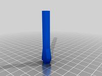
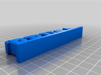
When you build the y-axis you should keep 80mm space between the nuts on the threaded rod. Well, you can measure, fix the nuts and later in the progress its not that exact anymore. Because of that you got spacers here. You need 2 times 2 of them you connect with each other on the rod. They keep the 80mm and as long as you hear no cracking plastic and see no gap between them and the nuts you are fine. (IMPORTANT: the .stl file in the package is for 0.4mm nozzles, if you got another one, please install openscad, open the .scad file, change the "nozzle" variable on top, render it and export a new stl file. You may also need to tweak the "flapfactor" variable so your slicer generates the flap correct.) [9-11]
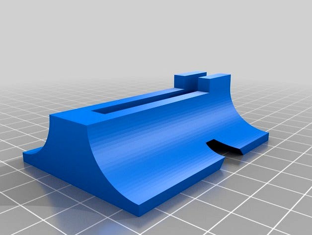
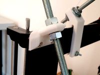
Marrying the portal with the y-axis is a bit tricky, because it is simply not standing :D
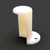
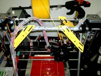
With the portalstand, you need two, you get something to make it stand by itself. Also even if it is not believable with this tiny plastic things, later the vibrations at printing(note the rondings for force redirection) but also the overall stability and precision is increased a lot. They may seem a bit tight at first look and you need force to place them(it may also crack a bit), but they should be very fix. [2-8]
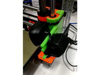
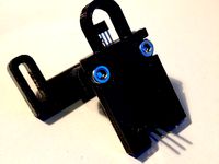
in the tutorial they say one should push the piece of filament until the end of fan shaft. Well you cannot do that, since the hole is simply ending somewhere but not channeling to the fan shaft. This causes problems with the fan holder at printing time. Here you find a 5015housing-MK3.stl with the hole how it should be [12]. If you want to use the tweaked x-carriage I mention below, also use 5015housing-MK3-tweaked.stl [13, 15]
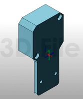
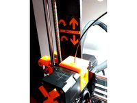
When the x-axis moves it may happen, that a force is applied to the printingfan. In this case the top nose of the x carriage may break. I changed the design a bit. x-carriage-tweaked.stl [14, 15] to use in combination with 5015housing-MK3-tweaked.stl [13, 15]
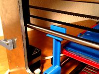
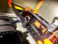
Whats not written in the guide, after assembly before calibrating z, since now you know everything is straight, you could do an "lcd: settings->auto home"(check the location of z-axis pushbutton before) and check the distance between the delivered, for me orange, plasticpats(see photo) with a caliper. For sure they are not equal. Just turn the nuts on the z-axis threaded rods at the top to adjust. This eases z calibration a lot... for sure only if everything is straight.
the plastic parts for calibrating z could be also tweaked by drawing quartermarks on them. maybe with numbers, so you know exactly which one is which one.
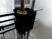
a nice stabilizer reducing the wobbling of the z axis threaded rods you can find here http://www.thingiverse.com/thing:1425056
{U} I designed it, its available here, but its not printed and/or installed.
When I got and assembled my Prusa i3 Plus Feb. 2016 Edition, I recognized the one or other thing I thought you could make better.
The parts are designed so you could use them at assembling, but also to upgrade the assembled printer.
For sure this parts are all printed with my feb 2016 prusa.
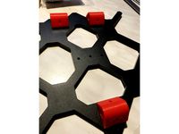
When you build the y-axis you should keep 80mm space between the nuts on the threaded rod. Well, you can measure, fix the nuts and later in the progress its not that exact anymore. Because of that you got spacers here. You need 2 times 2 of them you connect with each other on the rod. They keep the 80mm and as long as you hear no cracking plastic and see no gap between them and the nuts you are fine. (IMPORTANT: the .stl file in the package is for 0.4mm nozzles, if you got another one, please install openscad, open the .scad file, change the "nozzle" variable on top, render it and export a new stl file. You may also need to tweak the "flapfactor" variable so your slicer generates the flap correct.) [9-11]
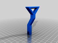
Marrying the portal with the y-axis is a bit tricky, because it is simply not standing :D
With the portalstand, you need two, you get something to make it stand by itself. Also even if it is not believable with this tiny plastic things, later the vibrations at printing(note the rondings for force redirection) but also the overall stability and precision is increased a lot. They may seem a bit tight at first look and you need force to place them(it may also crack a bit), but they should be very fix. [2-8]
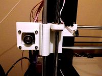
in the tutorial they say one should push the piece of filament until the end of fan shaft. Well you cannot do that, since the hole is simply ending somewhere but not channeling to the fan shaft. This causes problems with the fan holder at printing time. Here you find a 5015housing-MK3.stl with the hole how it should be [12]. If you want to use the tweaked x-carriage I mention below, also use 5015housing-MK3-tweaked.stl [13, 15]
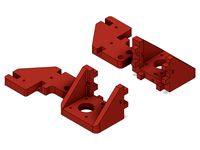
When the x-axis moves it may happen, that a force is applied to the printingfan. In this case the top nose of the x carriage may break. I changed the design a bit. x-carriage-tweaked.stl [14, 15] to use in combination with 5015housing-MK3-tweaked.stl [13, 15]
Whats not written in the guide, after assembly before calibrating z, since now you know everything is straight, you could do an "lcd: settings->auto home"(check the location of z-axis pushbutton before) and check the distance between the delivered, for me orange, plasticpats(see photo) with a caliper. For sure they are not equal. Just turn the nuts on the z-axis threaded rods at the top to adjust. This eases z calibration a lot... for sure only if everything is straight.
the plastic parts for calibrating z could be also tweaked by drawing quartermarks on them. maybe with numbers, so you know exactly which one is which one.
a nice stabilizer reducing the wobbling of the z axis threaded rods you can find here http://www.thingiverse.com/thing:1425056
Similar models
thingiverse
free
Microsoft LifeCam 3000 Z-axis mount for Prusa i3 MK3 by szabozsm
...ith a zip tie.
update:
the ear on the top seems to interfere with the z-calibration, so i removed it, and added a different one.
thingiverse
free

z nut stopper for p3steel x-carriage by ksevin
...lace spoiling the level. to solve this problem, i have designed a simple nut stopper that fits under the nut for 5 mm z-axis rod.
thingiverse
free
Sunhokey Prusa i3 Z axis carriage by Riez
...ttom z1 and z2 carriage for screw to fix the x axis smooth rod, you can use it or leave it as the hole for smooth rod is snug fit
thingiverse
free
Tool to level X-axis of Prusa i3 by mangtronix
... x-axis rod and y-axis rod. then you could hang one of the tools on each side of the x-axis rod and adjust them at the same time.
thingiverse
free
HIC Prusa I3 X-axis Motor Carriage *OFFSET Z-AXIS RODS* by Zeigbo
...rusa i3 and their x-axis carriage was warped, i recreated the part. please feel free to leave a comment if this part helped you.
thingiverse
free
Z axis height calibration by photocromax
...tands are engaged and pressed by the rod
lift z axis 20 mm
remove the stands
done, you're ready to print or level your bed :)
thingiverse
free
Geeetech i3 to MK3S Conversion by StanSPP
...iginal geeetech microswitch style endstop (note: i have not tested this myself as i'm using an inductive probe for my setup).
thingiverse
free
LM8UU housing for Prusa i3 MK3 by Papiertuete
...e "hole" for the lm8uu a bit "up" (when it's mounted) so that you don't loose too much z-axis length.
thingiverse
free
Prusa i3 Z Axis Stabilizer for board mount by mprobot
...crews into the board that the printer is mounted on.
requires one 5/16" x 36" rod cut in half, 8 nuts, and 4 screws.
thingiverse
free
Z nut retainer for MakerFarm Prusa i3 by TimeFramed
... the z axis threaded rods came "unseated" from the hex hole in the x idler and x motor housings.
this is my solution.

Feb
turbosquid
$85
Mexico City Feb 2021 Low Poly
...ad as c4d, blend, 3ds, wrl, dae, dxf, fbx, obj, stl, and usdz on turbosquid: 3d models for games, architecture, videos. (1694926)
turbosquid
$85
Busan City South Korea feb 2021 low poly
... c4d, blend, dxf, fbx, gltf, obj, stl, usdz, wrl, 3ds, and da on turbosquid: 3d models for games, architecture, videos. (1691728)
thingiverse
free
Feb 10 Demo by SurenReddyY
...feb 10 demo by surenreddyy
thingiverse
test
thingiverse
free

14 Feb Heart by 3dpiramit
...14 feb heart by 3dpiramit
thingiverse
14 şubat sevgililer gününe özel hediye
thingiverse
free
MOAI FEB vat rest by Scutum
... cause user must empty most of the resin before putting vat into this thing.
the lid is not airtight, it's just a dust cover.
thingiverse
free

Marble Track Spacers Big Holes Feb 2018 by MarbleKeeper
...nter to create a set of 10 spacers 10 brackets and 10 rail clips used with www.facebook.com/makeitallaboutmarbles marble tracks.
thingiverse
free

Anet lcd cover V2 FOR AFTER FEB 2017 versions by 3DTSUJ
...tsuj
thingiverse
just a slimmer version of my original one. only 5 grams now..
tabs r easier to file or sand now and fits better
thingiverse
free
Adjustable Z-endstop holder (for Prusa i3 Berlin Feb 2014) by mangtronix
...014 (newer models are different). i drilled out the holes for the endstop screws with a 2.5mm drill bit.
freecad source included.
thingiverse
free

SNAPFIT X endstop adjuster for Anet a8AFTER FEB 2017 or 20mm by 3DTSUJ
... but mine fits real snug..
if its too loose on you machine scale down 1 or 2% or vice versa
prints in about 10 mins at .2
enjoy
thingiverse
free

ANet LCD cover FOR AFTER FEB 2017 versions by 3DTSUJ
...e tabs r super thin.
new update its thinner now and tabs are thinner and fit easier
enjoy leave a comment on how it works for you
Tweaks
3d_export
$5

camera
...era
3dexport
the camera is done completely, but the textures need to be tweaked a little (because, i did everything in a hurry).
3d_export
$5
modern house
...modern house
3dexport
a great model for someone who would edit this model both inside and a little more tweaking on the outside
3d_ocean
$19

MaxMounts
...ds max, in a single click. several tweak-able parameters have been provided to get an infinite variety. the script also has an...
3d_ocean
$16

Mermaid
...olygons. made entirely in 3ds max 2015. it’s completely editable which means you can tweak whatever you need – if needed. not ...
3d_export
$45

Cyborg Head Bust V1
...ade with blender 2.9 render cycles and workbench, with some tweak and edit, its 3d print ready files ready: .blend .fbx .obj .stl
3d_ocean
$9

dragon (devil) character
...dragon devil character design. base model, with some minor tweaks you’ve got yourself a tiny little fellah. files included;...
3d_ocean
$15

Generic Laptop
...to a software, might need some texture linkings, and tweaks ...
3d_ocean
$9
ACOG Scope
...ll uv’s *parenting configured for easy movement/tweaking (moving the base will move everything) not included: normal/specular ...
3ddd
$1
Finn Juhl Poet Sofa
...e and hit render, nothing to cleanup, and dont need to tweak any material. texures are tilable. obj included for other platforms.
3d_ocean
$8

alien cartoon character
...from here with this alien. with a couple of tweaks here and there you’ve got your own alien! files...
I3
3d_export
$10
suv i3
...suv i3
3dexport
suv i3 2013 series
3d_ocean
$89

BMW i3 2012
...y, in real units of measurement, qualitatively and maximally close to the original. model formats: - *.max (3ds max 2008 scanl...
cg_studio
$99

BMW i3 20143d model
...
cgstudio
.3ds .c4d .fbx .lwo .max .obj - bmw i3 2014 3d model, royalty free license available, instant download after purchase.
cg_studio
$99

BMW i3 20123d model
...tudio
.3ds .c4d .fbx .lwo .max .mb .obj - bmw i3 2012 3d model, royalty free license available, instant download after purchase.
cg_studio
$99

BMW i3 20143d model
...tudio
.3ds .c4d .fbx .lwo .max .mb .obj - bmw i3 2014 3d model, royalty free license available, instant download after purchase.
humster3d
$75

3D model of BMW i3 2014
...
buy a detailed 3d model of bmw i3 2014 in various file formats. all our 3d models were created maximally close to the original.
humster3d
$40

3D model of Kitchen Set I3
...uy a detailed 3d model of kitchen set i3 in various file formats. all our 3d models were created maximally close to the original.
3d_ocean
$30
Kitchen set i3
...ensils oven plates shelves sink table ware
kitchen set i3 include 3d models: cooker, oven, sink, cupboards, table, chair, plates.
3d_ocean
$89

BMW i3 2014
...y, in real units of measurement, qualitatively and maximally close to the original. model formats: - *.max (3ds max 2008 scanl...
cg_studio
$99

BMW i3 Concept 20113d model
...i3
.3ds .c4d .fbx .lwo .max .obj - bmw i3 concept 2011 3d model, royalty free license available, instant download after purchase.
Prusa
turbosquid
$2
Frame Filament Guide Clip-On for Prusa Mk3
...rame filament guide clip-on for prusa mk3 for download as stl on turbosquid: 3d models for games, architecture, videos. (1634730)
3d_export
free
prusa i3 mk3s laser mount for opt lasers
...to learn more about the blue laser technology that conceived the cutting and engraving laser heads from opt lasers, please visit:
turbosquid
free
Prusa small printer adapter holder
...er for download as ipt, skp, dwg, dxf, fbx, ige, obj, and stl on turbosquid: 3d models for games, architecture, videos. (1642936)
3d_export
$30

geisha by jonathan adler
...** i did a 3d printing test in the prusa software, you can find it among the attached images.<br>exchange:<br>.blend...
thingiverse
free

Prusa without Prusa (rc2) by madless
...prusa without prusa (rc2) by madless
thingiverse
just the main part of prusa rc2 faceshield, without writing.
enjoy :)
thingiverse
free
Prusa by acejbc
...prusa by acejbc
thingiverse
prusa knob info
m3 8mm screw
thingiverse
free
Prusa house
...prusa house
thingiverse
how prusa house could look like...
thingiverse
free

Prusa Mk2 "Fake Prusa" LCD cover by anraf1001
...r by anraf1001
thingiverse
version of prusa's lcd cover with "fake prusa" instead of "original prusa"
thingiverse
free
Prusa stabilizator by gutiueugen
...prusa stabilizator by gutiueugen
thingiverse
prusa stabilizator
thingiverse
free
Keychain Prusa by rbarbalho
...keychain prusa by rbarbalho
thingiverse
keychain with text prusa.
Plus
turbosquid
$2
plus-plus puzzle and lego
...d model plus-plus puzzle and lego for download as stl and obj on turbosquid: 3d models for games, architecture, videos. (1662633)
3ddd
$1
Стенка Plus
...стенка plus
3ddd
plus , модная мебель
фабрика "модная мебель", модель plus
3ddd
$1
Спальня METIS plus
... hulsta , metis , спальня
спальня metis plus
design_connected
$11
be plus B+
...be plus b+
designconnected
blå station be plus b+ chairs computer generated 3d model. designed by börge lindau.
design_connected
$11
Bank Plus
...bank plus
designconnected
röthlisberger kollektion bank plus coffee tables computer generated 3d model. designed by atelier oi.
3ddd
$1

elos Plus
... candela
elos plus — мультифункциональный аппарат для проведения лазерного и ipl лечений
3ddd
$1
Calligaris Even Plus
...calligaris even plus
3ddd
calligaris
calligaris_chair_even plus
design_connected
$29

Basket Plus
...nconnected
photo-realistic 3d models of the basket plus bed from bonaldo for 3d architectural and interior design presentations.
3ddd
free
Artpole Faktum Plus
... артполе , панель
artpole faktum plus
размеры:
высота 625мм
ширина 800мм
глубина 17мм
3ddd
$1

Мария / Jazz Plus
...мария / jazz plus
3ddd
мария
кухня фабрики мария модель__jazz plus
2016
design_connected
$27

Sydney 2016
...sydney 2016
designconnected
poliform sydney 2016 computer generated 3d model. designed by massaud, jean-marie.
turbosquid
$15

Human-2016
...turbosquid
royalty free 3d model human-2016 for download as on turbosquid: 3d models for games, architecture, videos. (1175104)
3d_export
$5

polo sedan 2016
...polo sedan 2016
3dexport
polo sedan 2016 obj
turbosquid
$35

Towel 2016
... available on turbo squid, the world's leading provider of digital 3d models for visualization, films, television, and games.
turbosquid
$26
Kitchen 2016
... available on turbo squid, the world's leading provider of digital 3d models for visualization, films, television, and games.
turbosquid
$6

2016-07
... available on turbo squid, the world's leading provider of digital 3d models for visualization, films, television, and games.
turbosquid
$6

2016-08
... available on turbo squid, the world's leading provider of digital 3d models for visualization, films, television, and games.
turbosquid
$6

2016-010
... available on turbo squid, the world's leading provider of digital 3d models for visualization, films, television, and games.
turbosquid
$6

2016-09
... available on turbo squid, the world's leading provider of digital 3d models for visualization, films, television, and games.
turbosquid
$6

2016-06
... available on turbo squid, the world's leading provider of digital 3d models for visualization, films, television, and games.
Edition
turbosquid
$33
Natuzzi Editions
... available on turbo squid, the world's leading provider of digital 3d models for visualization, films, television, and games.
turbosquid
$29
Guitar_MJ-Edition
... available on turbo squid, the world's leading provider of digital 3d models for visualization, films, television, and games.
turbosquid
$20
Editable Fountain
... available on turbo squid, the world's leading provider of digital 3d models for visualization, films, television, and games.
3ddd
$1

Kueco Edition Palais
...kueco edition palais
3ddd
keuco
зеркальный шкаф kueco edition palais
design_connected
$16

369 Classic Edition
...369 classic edition
designconnected
walter knoll 369 classic edition computer generated 3d model.
3ddd
$1
Martz Edition
...martz edition
3ddd
martzedition
http://www.martzedition.com/a-500-3
3ddd
$1
Martz Edition
...martz edition
3ddd
martzedition
http://www.martzedition.com/b-400-3
design_connected
$25

Chester - Limited Edition
...nnected
established & sons chester - limited edition computer generated 3d model. designed by future systems, amanda levete.
3ddd
$1
KROKEN LIMITED EDITION
...d
rochebobois
autumn/winter collections 2012 rochebobois paris
kroken limited edition armchairhttp://m.roche-bobois.com
3ddd
$1
stilwerk limited edition
...stilwerk limited edition
3ddd
3000х1200х750