Thingiverse

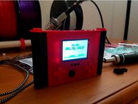
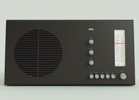
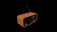
Multifunction radio by aenniw
by Thingiverse
Last crawled date: 3 years, 1 month ago
Multifinctional radio
current design is adapted to OrangePi Zero but can be migrated to use RaspberryPi ZeroW
design for inner usb-hub is for non hub that I had laying around so provided link to usb-hub is just for reference
based on the version of pc used for build wifi/bluetooth/dac dongles are not needed
design for CD/DVD drive is for slim version of notebook drives
for playback is used Volumio and Opi Zero uses img from Volumio Forum
script for updating playback cover to display volumio-album-art.sh
Opi Zero armbian config armbianEnv.txt
buttons control clone/build WiringOP and afterwards compile gpio-buttons.c
How-To
needed parts:PSU 12V2A,Amplifier,OrangePi Zero orRaspberryPi Zero,Flat USB-hub - optional,Wifi dongle - optional,USB audio card orDAC hat,TFT display,Bluetooth A2DP receiver - optional,StepDown module,RCA connectors,Power button,CD/DVD notebook drive - optional,IDE/SATA to USB - optional,Opi/Rpi fan,6 pen springs,4 Tactile Buttons,M2 screws
print case as whole or as 2 separate parts based on your printer volume
print all slider/pot parts 3 times, extends pots from amplifier with wires and mount them on sliders optionally add some grease
print all buttons related parts
and add tactile switches to buttons-case and secure them with hot/super glue
add pen spring to buttons-case and slowly insert button, adjust the spring with pliers
repeat for remaining buttons...
print all tape related parts
glue together tape-bottom and tape-top part add display to tape-tray add hot/super glue and cover with tape-tray-lid
do not forget to pass display cables through tray hole
cut 2 short pieces of wire bend then around tape-tray-joint but let be loose they will be used as spring that opens tape tray
insert tape-tray with bended wires optional glue them to tray for ease of assembling lock wires to slots on tape-bottom and insert tape-tray-joints
sand down tape-lock-pin insert it to slot on tape-top part, cut in half pen spring and insert each half on pins on tape-lock-pin
secure with tape until inserted into main body
add tape-eject buttons with spring and lock it with 2 pins from side
insert pot sliders, amplifier PSU and buck converter into left part of case and wire it up together
print remaining parts
add usb-hub usb-bottom part
add CD/DVD drive to case-right-bottom part and secure it with small screw from side
add Opi Zero to right part of case
add assembled buttons and tape parts and connect them to Opi Zero, optionally secure them with super/hot glue
join usb-bottom, case-right-bottom and usb-top parts add all electronics to them like usb-hub, wifi-dongle, usb-dac and bluetooth receiver
connect it to Opi Zero and insert int from bottom to right part of case and slowly slide it backwards... secure with screws from bottom
add case-left-bottom part and secure it with 4 screws
add back panel with AC socket, DC power switch and RCA connector that are connected to amplifier PSU and Opi Zero
optionally print wall mount parts to hang radio on the wall
Wiring
PINOUT: Display -> Raspberry Pi Zero
BL -> pin 12 (GPIO 18)
SCK -> pin 23 (GPIO 11)
MISO -> pin 21 (GPIO 9)
MOSI -> pin 19 (GPIO 10)
CS -> pin 24 (GPIO 8)
RST -> pin 22 (GPIO 25)
D/C -> pin 18 (GPIO 24)
VIN -> pin 17 (3.3v)
GND -> pin 20 (GND)
PINOUT: Display -> Orange Pi Zero
BL -> pin 15 (GPIO 3)
SCK -> pin 23 (GPIO 14)
MOSI -> pin 19 (GPIO 15)
CS -> pin 24 (GPIO 13)
RST -> pin 11 (GPIO 1)
D/C -> pin 13 (GPIO 0)
VIN -> pin 2 (3.3v)
GND -> pin 20 (GND)
Similar models
grabcad
free

Raspberry Pi Zero W - Sleek Case
... pins, display port, micro usb ports, and sd card. uses standard 2mm dowels to secure. intended for 1 time assembly (using glue).
thingiverse
free
RKade Mini by DMRadford
...tape to hold the battery leads in place during assembly. the risers in the prints will apply the pressure needed to make contact.
thingiverse
free

Raspberry Pi Zero + Ethernet / USB hat case (Pihole) by Woyta
...on between pi and hat was tight fit for me. if it is loose you will need piece of double sided tape or change scale of that part.
thingiverse
free

Raspberry Pi Zero / Zero W USB Dongle Case by Tom90
...ing this working with wiring and programming info found here:
https://www.novaspirit.com/2016/10/18/raspberry-pi-zero-usb-dongle/
thingiverse
free

Housing for Pi Zero with MakerSpot stackable USB-hub by Antalpromille
...t needed with this.
edit: 2017-10-15, added a new top-part without holes for heat sink and gpio header (requested by maferreira).
thingiverse
free

Raspberry Pi Zero W Case USB Dongle by joseigbv
...raspberry pi zero w case usb dongle by joseigbv
thingiverse
convert your raspberry pi zero into a usb dongle.
thingiverse
free

Raspberry pi Zero USB dongle by darkdecenet
...raspberry pi zero usb dongle by darkdecenet
thingiverse
this a usb dongle case for raspberry pi
thingiverse
free

USB Dongle Case for Raspberry Pi Zero W by kapakahi
...soldering wires to pads. use #4 3/8" screws or similar in...
thingiverse
free

Case for Raspberry Pi Zero + Pi Zero USB Docking Hub by Xav987
... micro usb port from the raspberry pi zero are inaccessible with the case, because you have to use the port from the hub instead.
thingiverse
free

USB-RS232 dongle cover by Stoney
...all case for pl2303 based usb dongles with either straight or bent header pins.
small hole allows led visibility.
glues together.
Aenniw
thingiverse
free

HUAWEI P9 Lite tripod mount by aenniw
...huawei p9 lite tripod mount by aenniw
thingiverse
layer height 0.2, supports needed
thingiverse
free

DPS3005 - MeanWell RS-50-5 by aenniw
...dps3005 - meanwell rs-50-5 by aenniw
thingiverse
small bench psu cover for meanwell rs-50-5 and dps3005
thingiverse
free

SKARSTA - motorized table by aenniw
...hicker pcb
added additional screw mount to display panel
slimmed display + keypad case
3-5-19
synced with github repo model files
Multifunction
3d_export
free

Multifunctional Shader
...al shader
3dexport
multifunctional shader (group of nodes) allows you to quickly and easily customize materials for your models.
3d_export
$12

Modern multifunctional hall
...modern multifunctional hall
3dexport
modern multifunctional hall
turbosquid
$10

Multifunctions Table
...oyalty free 3d model multifunctions table for download as skp on turbosquid: 3d models for games, architecture, videos. (1609324)
turbosquid
$15

Multifunctional Blender
...del multifunctional blender for download as obj, c4d, and fbx on turbosquid: 3d models for games, architecture, videos. (1261665)
turbosquid
$49

multifunctional building
... available on turbo squid, the world's leading provider of digital 3d models for visualization, films, television, and games.
turbosquid
$49

MultiFunction Robot
... available on turbo squid, the world's leading provider of digital 3d models for visualization, films, television, and games.
turbosquid
$90

Multifunctional optical tractor
...d model multifunctional optical tractor for download as sldas on turbosquid: 3d models for games, architecture, videos. (1245127)
turbosquid
$28

Multifunctional Smart Navigator
...ifunctional smart navigator for download as max, obj, and fbx on turbosquid: 3d models for games, architecture, videos. (1687298)
turbosquid
$29

Multifunctional Bench 2
...ultifunctional bench 2 for download as 3ds, max, obj, and fbx on turbosquid: 3d models for games, architecture, videos. (1327204)
turbosquid
$55

Multifunction Chargeable Drill
... available on turbo squid, the world's leading provider of digital 3d models for visualization, films, television, and games.
Radio
archibase_planet
free
Radio
...radio
archibase planet
radio
radio - 3d model for interior 3d visualization.
archibase_planet
free
Radio
...radio
archibase planet
radio
radio - 3d model for interior 3d visualization.
3d_export
$10
radio
...radio
3dexport
radio 3d, ojb
archibase_planet
free
Radio
...radio
archibase planet
radio set wireless receiver wireless set
radio 2 - 3d model (*.gsm+*.3ds) for interior 3d visualization.
archibase_planet
free
Radio
...radio
archibase planet
radio set wireless receiver wireless set
radio 7 - 3d model (*.gsm+*.3ds) for interior 3d visualization.
archibase_planet
free
Radio
...radio
archibase planet
radio set wireless receiver wireless set
radio 10 - 3d model (*.gsm+*.3ds) for interior 3d visualization.
3d_ocean
$9
Vintage Radio
...vintage radio
3docean
old radio radio set vintage
this is a vintage radio modeled to help in interior design arrangements.
3d_ocean
$8
Radio Branu
...radio branu
3docean
detail radio vintage
vintage radio with detail
3d_export
$5
radio
...radio
3dexport
turbosquid
$25

Radio
...o
turbosquid
royalty free 3d model radio for download as max on turbosquid: 3d models for games, architecture, videos. (1203794)