Thingiverse

MPMD Effector Part Cooling Vents and Casing
by Thingiverse
Last crawled date: 4 years, 3 months ago
Notes:
I have not done a comparison of this version vs the stock design. It was really just an exercise in design. If I had been on the ball I would have had some 'Before' prints so I could make a comparison of print quality.
After having the effector apart as many times as I did over the last week, I really don't feel like reassembling the stock effector just to do this. Please feel free to do your own tests to see if the new design has any impact (good or bad) on print quality.
I have been printing with the new design and I haven't run into any issues so far.
If you do print out the parts I would strongly suggest that you fit all pieces carefully before assembly. It is much easier to ensure that parts are well fitted while the pieces are off the machine rather than trying to do it while on the effector.
Summary
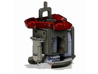
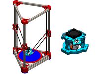
I have made several different effectors and heat sink casings for the MPMD. This is a new one that incorporates a couple of different part cooling vents for the stock effector.
The different parts can be combined in a variety of ways although the main idea was to provide rear part cooling vents with air supplied using an air pump.
In this case the design uses an air pump that supplies air to the vents through 6x8mm silicone tubing. I have only included the effector parts for this model as the air pump can be anything that supplies adequate air flow and can attach to 6x8 tubing.
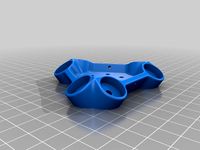
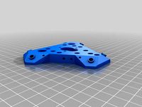
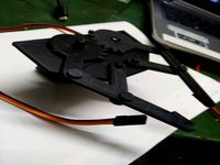
The parts that are included are:1. Heat Sink Casing that replaces the existing black one. This one fastens to the effector using 2 - M3 machine screws. It has a collar that cradles the bowden connector to alleviate any excess stresses on the connection to the heatsink. Extra support for the bowden connector can also be gained by utilizing the holes in the collar for tightening bolts.
This casing also has no ears to hold the fan clips. I was getting quite frustrated trying to clip and unclip the spring clips so I decided to eliminate them. That means that the existing fan vent will no longer fit on the effector.
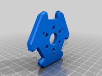
2. Front Fan Shrouds (3)i.) one "Standard" design that just utilizes the front fan and can be used without any base vents or with the double vent base.ii.) one that allows excess air from the heatsink fan to be channelled as part of the part cooling vent and is used with the triple vent baseiii.) one that directs the excess air away from the nozzle in cases where you may not want any part cooling. It can be used with either or none of the vent bases.
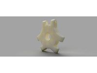
3. Part Cooling base vents (3)i.) a double vent that supplies air to the back area of the nozzle and are fed air using an air pump and the 6x8 silicone tubing.ii.) a triple vent that supplies air to the back and front of the nozzle and can be used with 3 air pump hoses, or 2 for the back and the front can be fed using the 2nd front fan shroud design.iii.) an updated version of the triple vent. This may provide better part cooling but I have not tested these for effectiveness. This version sits very close to the heat block and actually touches my silicone sock. I have been printing with it and it has been holding up.
All my parts have only been printed in PLA.
4. Rear Manifolds (3)
These are holders for small side duct fans (3010) if you decide not to use an air pump.i.) a single fan unit that can be used in conjunction with a 30x10 side duct fan.
I have not tested the air flow for this unit, but I have tested the fit. Basically mount a 30x10 side duct fan to this units and splice it to the existing fan wire (or run your own power.) The fan will then vent air through the back two nozzles of either the double or triple vent.ii.) a double fan unit that can be used in conjunction with 2 - 30x10 side duct fans. This one mounts along the back and sides and provides air for each side duct from individual fans. Like the single fan unit, the two fans will need to be spliced into the existing fan wires or you need to run their own lines.iii.) another double fan unit.
This is a combination of the two previous rear manifolds. It uses 2 fans but they are mounted at the back at angles. The wiring will be the same as the other double fan manifold.
The triple or double vent bolt to the bottom of the effector, and will require you to ensure that you have positioned the nozzle so that it will protrude about 1 or 2mm beyond the base (lowest point) of the vents. Positioning the nozzle height is important as the vents can interfere with levelling, if the nozzle is too high. If the nozzle is too low the sock (if used) or block may interfere with the airflow.
Printing
I print all items with their bottoms to the bed except the Heat Sink Casing which I lie on its back. I set supports to touching bed only and in most cases I only use a skirt.
On the "Standard" style front vent, since the surface touching the bed is so small I use a large brim to ensure it does not get knocked as it prints closer to the top.
You may be able to get away with no supports but there are a few overhangs which need them and the supports I used were easy to remove and not very large.
Warning
Due to the tight tolerances be sure to test fit and scale when necessary (depending on the dimensional accuracy of your printer.)
For all parts, especially the Front Cooling Vent and the Rear Manifold, test fit before assembling on the effector. I also place all bolts and fit nuts prior to assembly as well to ensure that everything fits well.
I have not done a comparison of this version vs the stock design. It was really just an exercise in design. If I had been on the ball I would have had some 'Before' prints so I could make a comparison of print quality.
After having the effector apart as many times as I did over the last week, I really don't feel like reassembling the stock effector just to do this. Please feel free to do your own tests to see if the new design has any impact (good or bad) on print quality.
I have been printing with the new design and I haven't run into any issues so far.
If you do print out the parts I would strongly suggest that you fit all pieces carefully before assembly. It is much easier to ensure that parts are well fitted while the pieces are off the machine rather than trying to do it while on the effector.
Summary
I have made several different effectors and heat sink casings for the MPMD. This is a new one that incorporates a couple of different part cooling vents for the stock effector.
The different parts can be combined in a variety of ways although the main idea was to provide rear part cooling vents with air supplied using an air pump.
In this case the design uses an air pump that supplies air to the vents through 6x8mm silicone tubing. I have only included the effector parts for this model as the air pump can be anything that supplies adequate air flow and can attach to 6x8 tubing.
The parts that are included are:1. Heat Sink Casing that replaces the existing black one. This one fastens to the effector using 2 - M3 machine screws. It has a collar that cradles the bowden connector to alleviate any excess stresses on the connection to the heatsink. Extra support for the bowden connector can also be gained by utilizing the holes in the collar for tightening bolts.
This casing also has no ears to hold the fan clips. I was getting quite frustrated trying to clip and unclip the spring clips so I decided to eliminate them. That means that the existing fan vent will no longer fit on the effector.
2. Front Fan Shrouds (3)i.) one "Standard" design that just utilizes the front fan and can be used without any base vents or with the double vent base.ii.) one that allows excess air from the heatsink fan to be channelled as part of the part cooling vent and is used with the triple vent baseiii.) one that directs the excess air away from the nozzle in cases where you may not want any part cooling. It can be used with either or none of the vent bases.
3. Part Cooling base vents (3)i.) a double vent that supplies air to the back area of the nozzle and are fed air using an air pump and the 6x8 silicone tubing.ii.) a triple vent that supplies air to the back and front of the nozzle and can be used with 3 air pump hoses, or 2 for the back and the front can be fed using the 2nd front fan shroud design.iii.) an updated version of the triple vent. This may provide better part cooling but I have not tested these for effectiveness. This version sits very close to the heat block and actually touches my silicone sock. I have been printing with it and it has been holding up.
All my parts have only been printed in PLA.
4. Rear Manifolds (3)
These are holders for small side duct fans (3010) if you decide not to use an air pump.i.) a single fan unit that can be used in conjunction with a 30x10 side duct fan.
I have not tested the air flow for this unit, but I have tested the fit. Basically mount a 30x10 side duct fan to this units and splice it to the existing fan wire (or run your own power.) The fan will then vent air through the back two nozzles of either the double or triple vent.ii.) a double fan unit that can be used in conjunction with 2 - 30x10 side duct fans. This one mounts along the back and sides and provides air for each side duct from individual fans. Like the single fan unit, the two fans will need to be spliced into the existing fan wires or you need to run their own lines.iii.) another double fan unit.
This is a combination of the two previous rear manifolds. It uses 2 fans but they are mounted at the back at angles. The wiring will be the same as the other double fan manifold.
The triple or double vent bolt to the bottom of the effector, and will require you to ensure that you have positioned the nozzle so that it will protrude about 1 or 2mm beyond the base (lowest point) of the vents. Positioning the nozzle height is important as the vents can interfere with levelling, if the nozzle is too high. If the nozzle is too low the sock (if used) or block may interfere with the airflow.
Printing
I print all items with their bottoms to the bed except the Heat Sink Casing which I lie on its back. I set supports to touching bed only and in most cases I only use a skirt.
On the "Standard" style front vent, since the surface touching the bed is so small I use a large brim to ensure it does not get knocked as it prints closer to the top.
You may be able to get away with no supports but there are a few overhangs which need them and the supports I used were easy to remove and not very large.
Warning
Due to the tight tolerances be sure to test fit and scale when necessary (depending on the dimensional accuracy of your printer.)
For all parts, especially the Front Cooling Vent and the Rear Manifold, test fit before assembling on the effector. I also place all bolts and fit nuts prior to assembly as well to ensure that everything fits well.
Similar models
thingiverse
free

MPMD Double Fan Part Cooler by ksihota
...r fan can be used for this purpose.
to control the fans using your slicer and gcode, you need to upgrade your firmware to marlin.
thingiverse
free

Integrated Fan Duct for E3D-v6 hotend by DWONH
... check it, visit page below.http://www.thingiverse.com/thing:1292038
12/5/2016 update:
i added double sided bracket upon request.
thingiverse
free

Tronxy XY-2 Pro Cooling Fan Duct by Shtoobs
...i have included internal fins to direct air where it is needed. i made this duct with a low profile and maximum cooling ability.
thingiverse
free

AM8/E3D Hemera Rear Mount Part 5015 Cooling Fan - Mount and Duct
...hat doesn't block the fan.
the pillow block will likely need to be tapped to fit the screw that you use. i used an m4 screw.
thingiverse
free

Around-the-nozzle cooling ring for RepRap (Adrians Geeared extruder) by ahmetcemturan
...d a bracket to screw it onto the lower x-carriage..
i also used an aquarium air pump instead of a fan and duct for the ir supply.
thingiverse
free

Lulzbot mini - dual fan plus heat sink fan by gigrichj_2145
...reat.
to print the dual fan, print as shown in the stl picture with support from the build plate to bottom of fan only....
cheers
thingiverse
free

FT5 Fan Duct by Rbuilder1
... and is not melting while printing pla, you might have to test if higher temps will influence the fan.
it is made for a 40mm fan.
thingiverse
free

ANYCUBIC MEGA S Fan Duct
...did to modify your own circular duct in a similar ...
thingiverse
free

Easythreed X1 circular fan duct part cooler by calex0
...double-sided tape
you use a plastic fastener
i also included the sketchup project in case you want to make changes to the model.
thingiverse
free

Circular air cooling vent for Geeetech i3 nozzle
...for the most popular design. i aligned it with the duct nozzle by lifaon74 and merged the two pieces using blender and meshmixer.
Mpmd
thingiverse
free

MPMD Spool Forks - single piece
...mpmd spool forks - single piece
thingiverse
mpmd filament spool
thingiverse
free

MPMD Replacement Spool Holder by dscpt
...mpmd replacement spool holder by dscpt
thingiverse
basic replacement mpmd rear mounted spool holder.
thingiverse
free

MPMD feet
...e vibration absorption.
i used some double sided tape to assemble them to the printer in case i ever need to unscrew the endcaps.
thingiverse
free

MPMD Leg
...iverse
this is yet another leg model for monoprice mini delta, because i did not like other models of it. stock screws are okay.
thingiverse
free

MPMD fan mount for radiator
...mpmd fan mount for radiator
thingiverse
for standard cooler 30mm
thingiverse
free

mpmd 40mm fan shroud by lsirhc
...
thingiverse
mpmd 40mm fan shroud remix of ericrobodox stock shroud.
i haven't tried it yet, it may interfere with the arms.
thingiverse
free

MPMD (Mini Delta) bowden slider - endstop shield
....
this slider solved it.
printable on mpmd. the one piece is not possible to print on mpmd and it is not easy to get it in place.
thingiverse
free

MPMD top spool holder
...mpmd top spool holder
thingiverse
slip this on top of the monoprice mini delta printer and put a spool on top.
thingiverse
free

MPMD Frame Column Shield Remix
...m tall, 1.6mm thick in most places, 0.8mm on the ends.
mpmd shield. check out my enclosure as well, they work together perfectly.
thingiverse
free

Glass Bed Retainer - Monoprice Mini Delta (MPMD) by bLITzJoN
...op. this requires a larger printer, so if the mpmd is all you have then look at the glass bed clip - monoprice mini delta (mpmd).
Effector
3d_ocean
$5

Radial Sound Effector
...e spheres will expand with your song. fully customisable, change the color, the size of the spheres or even put in different s...
3d_ocean
$12

3D Customizable Puzzle Set (16x10)
...mograph compatible (you can effect the pieces with mograph effector) - included also a non-mograph version with...
thingiverse
free
Effector by olo2000pm
...effector by olo2000pm
thingiverse
effector
thingiverse
free
CERAMBOT-Effector
...cerambot-effector
thingiverse
cerambot-effector
thingiverse
free

modulize effector by candyasdf
...ulize effector by candyasdf
thingiverse
mount things on effector with m3 screws
effector radius : 25.4mm
rod arm distance : 40mm
thingiverse
free
Delta Effector by zavier
...delta effector by zavier
thingiverse
delta effector with radial fan 50 and bltouch
thingiverse
free
D810 Effector by WhiteTiger13
...d810 effector by whitetiger13
thingiverse
this is d810 effector for d810 without autocalibration, and also cap for it.
thingiverse
free
Effector for Delta Printer
...effector for delta printer
thingiverse
effector for delta printer (3 color)
using diamond hotend
thingiverse
free
Delta effector magnetic by fpassos
...delta effector magnetic by fpassos
thingiverse
effector for e3dv6 hotend. i needed put the spheres (10mm) on the effector.
thingiverse
free
End Effector Gripper
...end effector gripper
thingiverse
end effector gripper
for a robotic arm
uses mg995 servo motor
Vents
archibase_planet
free

Vent
...vent
archibase planet
aeration venting home equipment
diffuser vent - 3d model for interior 3d visualization.
archibase_planet
free

Vent
...vent
archibase planet
cooker hood cooking hood
vent - 3d model for interior 3d visualization.
archibase_planet
free

Vent
...vent
archibase planet
cooker hood cooking hood
vent atlantica - 3d model for interior 3d visualization.
archibase_planet
free

Vent
...vent
archibase planet
cooker hood cooking hood
vent half frame - 3d model for interior 3d visualization.
archibase_planet
free

Vent
...vent
archibase planet
cooker hood cooking hood
vent - 3d model (*.gsm+*.3ds) for interior 3d visualization.
archibase_planet
free

Vent
...vent
archibase planet
cooker hood cooking hood kitchen equipment
vent - 3d model for interior 3d visualization.
archibase_planet
free

Vent
...vent
archibase planet
damper diffuser air gate
vent grate n100807 - 3d model for interior 3d visualization.
archibase_planet
free

Vent
...vent
archibase planet
cooker hood cooking hood
vent - 3d model (*.gsm+*.3ds) for interior 3d visualization.
turbosquid
$10

Vent
...nt
turbosquid
royalty free 3d model vent for download as fbx on turbosquid: 3d models for games, architecture, videos. (1143454)
turbosquid
$2

Vent
...nt
turbosquid
royalty free 3d model vent for download as obj on turbosquid: 3d models for games, architecture, videos. (1323956)
Cooling
turbosquid
free

Cool Inc. Cool Box
... available on turbo squid, the world's leading provider of digital 3d models for visualization, films, television, and games.
3d_export
$5

cool penguin
...cool penguin
3dexport
cool penguin
turbosquid
$1

cooling
... available on turbo squid, the world's leading provider of digital 3d models for visualization, films, television, and games.
3d_export
$26

cooling tower
...ers.<br>model with full detail in real size. all nodes and bolted connections are built. it was designed for nuclear power.
3ddd
$1

Mantra Cool
...14 версиях и obj-файл, а также материал для включенного и для выключенного светильника. turbosmooth/meshsmooth при необходимости.
3d_export
$5

cool electric guitar
...cool electric guitar
3dexport
cool electric guitar
turbosquid
$5

Cooling glass
...quid
royalty free 3d model cooling glass for download as obj on turbosquid: 3d models for games, architecture, videos. (1193829)
turbosquid
$30

CPU Cooling
...royalty free 3d model cpu cooling for download as max and fbx on turbosquid: 3d models for games, architecture, videos. (1386263)
turbosquid
$5

Cool CLoud
...
royalty free 3d model cool cloud for download as ma and obj on turbosquid: 3d models for games, architecture, videos. (1572300)
3d_export
$5

table cooling fan
...table cooling fan
3dexport
table cooling fan made of black plastic. individual small size cooling fan for office desk.
Casing
3d_export
$1
case
...case
3dexport
case
archibase_planet
free
Case
...case
archibase planet
showcase show-case glass case
glass-case + cakes - 3d model for interior 3d visualization.
archibase_planet
free
Case
...case
archibase planet
showcase show-case glass case
glass-case for chips - 3d model for interior 3d visualization.
archibase_planet
free
Case
...case
archibase planet
case shelving drawer
case - 3d model for interior 3d visualization.
archibase_planet
free
Case
...case
archibase planet
case rack locker
case - 3d model for interior 3d visualization.
archibase_planet
free
Case
...case
archibase planet
case drawer kitchen furniture
case - 3d model for interior 3d visualization.
archibase_planet
free
Case
...case
archibase planet
case cupboard shelving
glass case - 3d model for interior 3d visualization.
archibase_planet
free
Case
...case
archibase planet
case handbag suitcase
case - 3d model (*.gsm+*.3ds) for interior 3d visualization.
archibase_planet
free
Case
...case
archibase planet
case suitcase
case 5 - 3d model (*.gsm+*.3ds) for interior 3d visualization.
archibase_planet
free
Case
...case
archibase planet
locker case dresser
case - 3d model (*.gsm+*.3ds) for interior 3d visualization.
Part
3d_export
$5
Parts
...parts
3dexport
parts
3d_export
$5
Part
...part
3dexport
part
3d_export
$5

Part
...part
3dexport
machine part
3d_export
$65
Part
...part
3dexport
simple rendering of the scene file
3d_export
$65
Part
...part
3dexport
simple rendering of the scene file
3d_export
$30

fan part
...fan part
3dexport
this is a part of fan of pedastal
3d_export
$10
machine parts
...machine parts
3dexport
3d part modeling work ,contact for 3d work
turbosquid
$59

Mechanical Part
...id
royalty free 3d model mechanical part for download as c4d on turbosquid: 3d models for games, architecture, videos. (1410833)
turbosquid
$17
Road parts
...bosquid
royalty free 3d model road parts for download as 3ds on turbosquid: 3d models for games, architecture, videos. (1192967)
turbosquid
$9

Cutter Parts
...squid
royalty free 3d model cutter parts for download as stl on turbosquid: 3d models for games, architecture, videos. (1220010)