Thingiverse
Mouse Trap With Wifi (or without) by ReallyBigTeeth
by Thingiverse
Last crawled date: 4 years, 8 months ago
If you like what you see here, consider leaving a tip.
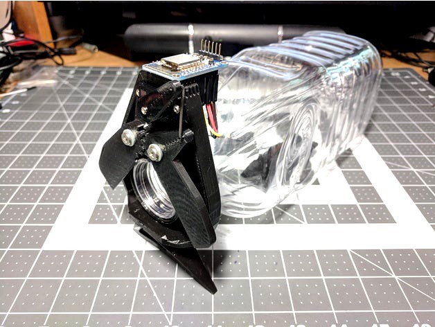
A totally overkill (without any killing) mousetrap. When a mouse or other small varmint steps on a switch inside the bottle, a microcontroller activates a servo to close the door (or doors) on the bottle, trapping the critter inside and sending an alert over WiFi letting you know that the trap has been sprung. This project was built using an Adafruit Huzzah ESP8266 WiFi microcontroller breakout board, but could be controlled using any microcontroller capable of digital/analogue input and servo control. I have included code written for and tested on an Adafruit Huzzah ESP8266 (WiFi), and an Adafruit Pro Trinket 5v (No WiFi).Updates:
2018 Dec 15
Added web button to remotely reset the trap.
2019 Aug 22
Added a counterbalanced single door. I recommend this over the dual door or single unbalanced door. Uses two long M4 or equivalent screws for counterweight.
Parts List:
Microcontroller - Adafruit Huzzah ESP8266 (WiFi) or Adafruit Pro Trinket 5v (no WiFi) ~$11 - $14 CAD
Servo - 2.5g Goteck Metal Gear Micro Servo GS-9025MG ~$9 CAD
Plastic bottle with 1.5" neck - common juice bottle size. (Ocean Spray, Sunripe, etc)
24 AWG silicon insulated wire (do not use wire with soy based insulation as rodents will chew on it) ~$1.50 CAD for 3m
Shrink tubing for 24 AWG wire
Music wire - 1/32", 3/64", or 1/16" should work
2x 6-32 3/4" screws and washers
2x 6-32 3/8" screws and washers - it may be helpful to go with longer screws and cut/grind them to length
5v DC Power supply - 1A minimum
#6 Ring Terminal (optional) ~$2.50 CAD for pack of 6
Female jumper wires (optional) ~$2.50 CAD for pack of 20
Tools & Supplies:
A computer - for modifying and upload code to your microcontroller.
FTDI Cable - for uploading code to the microcontroller.
Soldering Iron and solder.
Butane/propane torch, lighter, or heat gun (optional).
Screw driver(s).
Glue - I recommend two part epoxy with 30 - 45 min working time.
Pliers - for bending the servo control rod.
Drill and drill bit - for resizing holes in the servo horns.
Barbecue skewer
Instructions:
Let's get your microcontroller programmed before any wires get connected. Check out the Adafruit Huzzah ESP8266 setup guide, or the Adafruit Pro Trinket setup guide. These guides will get you familiar with your microcontroller, walk you through driver installation, Arduino IDE installation and software library setup, and show you how to program your microcontroller. When you're comfortable with how everything works, come back here for the next step.
For Adafruit Pro Trinket (and other non WiFi boards):
Open the "Mouse_Trap_Pro_Trinket.ino" file in your Arduino IDE and upload the code to the Pro Tinket. The value on lines 27 and 28 is a mid point to centre the servo before attaching the servo horn. These values will be changed later.
For Adafruit Huzzah ESP8266:
Open the "Mouse_Trap_Huzzah_ESP8266.ino" file in your Arduino IDE enter your network's SSID on line 41, your network password on line 42, give your Huzzah a static IP address on line 45, also enter your network's gateway and subnet on line 45 and hit the upload button to send the code to your Huzzah ESP8266. The value on lines 56 and 57 is a mid point to centre the servo before attaching the servo horn. These values will be changed later.
When the Huzzah board is powered up the following LED sequences should occur: Solid Red and blinking Blue LED means the board is trying to connect to your Wifi, Red and Blue alternating blinking lets you know the board is connected to your WiFi and the trap door(s) is/are about to open, Solid Blue LED indicates the trap is ready and waiting to catch something.
The board needs to be connected to WiFi in order for the trap to work properly. If the connection is interrupted, the board will run the reconnect function, preventing the microcontroller from checking the status of the switch. Iv'e tried writing the code a few different ways to prevent this from happening but haven't had any luck so far. See the troublshooting guide at the end of these instructions.
Print the switch base, switch top, and the contact template. Run wire through the middle hole in the switch base and then through the switch top.
Use the contact template to trace a circle on some thin sheet metal and cut the circle out using some tin snips. The metal should be electrically conductive and solderable. If using a soup can lid, remove the plastic coating from the inside of the lid with sand paper before soldering.
Test fit the contact plate in the switch top. Cut, sand, or file away material until the contact fits in the switch top. Mark the orientation of the circle where the wire will be soldered.
Solder the end of the wire to the contact and insert the contact in to the switch pulling the slack out of the wire.
Apply glue around the edge of the contact plate, in the wire channel, and glue the switch top to the switch base. I use two part epoxy with 30 - 45 min working time.
The switch top should make contact with the switch base with 8 - 12 grams of force ( about the weight of 2 or three Canadian quarters). You can pull up on the switch top to bend the spring portion and give the switch more tension/travel, or use a torch to slightly melt the spring portion to give the switch less tension/travel, or adjust the length of the contact screw when the switch is installed in the bottle.
I heated a centre punch with a torch to melt holes in the bottle for ventilation, and three holes to mount the switch and pass the wire though. Measure twice and cut... err... melt once.
Crimp a ring terminal to the end of some wire. The wire will need to reach the controll board when it is installed, so cut it a few centimetres longer then the reach to the bottle opening and trim it to length later.
Secure the switch to the inside of the bottle using the 3/8" 6-32 screws placing the ring terminal on the screw at the contact end of the switch. I used a barbecue skewer to hold the switch in place wile fastening the first screw. Make sure the screw on the contact side of the switch will touch the contact plate when the switch is depressed. If the contact plate is touching the screw without being pushed down, cut or grind the screw to the correct lenght, or add washers to back it away from the contact plate.
Set the bottle and switch aside for now. It's time to assemble the working end of the trap. Decide weather you want a base plate with or without legs, and single door or double door and print the parts along with the threaded ring. If using a Goteck Metal Gear servo, also print the servo horn. I prototyped this trap using a hitec hs-55 servo, but found the Goteck servo to be smoother, more reliable and accurate at a comparable price.
Place the threaded ring in the base plate, then screw the door(s) to the base plate using 6-32 3/4" screws and washers. Tighten the screw until the doors will no longer swing freely, then back the screws off just enough to let the doors swing without any resistance. Next, insert the servo and screw it to the base plate.
To keep things tidy, I cut three female jumper wires in half, shortened the servo leads, and soldered the jumper wires to the servo leads and covered the joint with shrink tube. You could do without the jumper wires by soldering the servo leads directly to the microcontroller board.
If using a Huzzah ESP8266 breakout board, attach the servo's black wire to ground, red to V+, and yellow to pin 12. For a Pro Trinket, the black wire goes to ground, red to BUS, and yellow to pin 9.
Place the base plate on the bottle and tighten the threaded ring making sure to align the feet with the bottle face that has the switch.
Drill the holes in the servo control horn and the holes in the door(s) control arm slightly larger than the music wire. Bend and cut a piece of music wire to make a z shaped push rod approximately 24mm in length, and insert one end in the servo horn and and the other in the the door(s) control arm. Apply power to the microcontroller and let the servo center itself. Open the door(s) halfway and put the servo control horn on the servo and use the screw that came with the servo to hold it in place.
Now open the code in the Arduino IDE again to set the servo positions for fully open and fully closed. This will be a trial and error process that will take some time to get just right. First increase the servoOpen parameter by increments of 10 on line 56 of the Huzzah code, or line 27 of the Pro Trinket code and upload the code to your micro controller. Repeat this process until the door(s) just clear the opening of the bottle. Then decrease the value by increments of one or two to get the open position just right. The edge of the door(s) shouldn't go beyond the inner opening of the bottle.
Next, decrease the servoClosed parameter by increments of 10 on line 57 of the Huzzah code, and bridge the second ground pin with pin 14, or line 28 of the Pro Trinket code, and bridge ground with pin 11, and upload the code to your microcontroller. Repeat this until the servo closes the door fully and you can hear the servo binding. Now increase the value by one or two until the door is fully close without any servo binding.
One wire from the switch can be cut to length and attached to pin 14 on the Huzzah ESP8266, or pin 11 on the Pro Trinket. The other wire from the switch can be cut to length and connected to the second ground pin of the Huzzah ESP8266. The Pro Trinket only has one ground pin, so you could use a two pin jumper extension to attach the servo wire and switch wire to the ground pin (which is what I did), or modify the code to set a digital pin low and use it as a ground pin for the switch. Again, I used female jumper wires for these connections.
Bait the trap. The internet seems to agree that peanut butter is the best bait for mice, and I've found it to work well. I use a barbecue skewer to place a ball of peanut butter in the bottom of the bottle. Try not to get any on the sides of the bottle; a mouse may get a meal without having to walk over the switch. I'm thinking that using 1oz paper cups, often found in fast food restaurants, would do a great job of containing the bait, making cleanup much easier. I didn't clean the bottle after catching a couple mice and after about a month a new mouse came along but didn't show any interest in the trap until I cleaned it and baited it with some fresh peanut butter.
If you used a Pro Tinket, your done! Just set the trap where you know mice frequently pass by. You can use a USB power adaptor with a micro USB calbe, or a battery with a sufficiently large capacity to keep the trap powered until it's time to recharge. Check the trap at least once a day. You can set up a networked camera to check the trap from your computer, phone, or tablet.
If you used a Huzza ESP8266, you'll need to power the board using an FTDI cable or cut the end off a USB cable and solder female jumber wires to the positive and negative wires and connect them to the 5v and ground pins of the FTDI header.
With the board powered up, log in to a web browser and type the IP address of the Huzzah in to the browser's address bar to check the status of the trap. It's still a good idea to do a physical check of the trap daily just to be sure everything is working.
Troubleshooting the Huzzah ESP8266:
In the code for the Huzzah board, there are lines that give output to the Arduino IDE serial monitor. Uncomment the line that starts with "Serial.begin", and any line that starts wih "Serial.println" by removing the "//" at the beginning of the line. Then go to Tools --> Serial Monitor, and upload the code to your Huzzah. Some helpful info will show up to help you figure out what is going wrong with the code.
If the board will not connect to your network when power is first applied, try disconnecting power and plugging it back in. It seems that timing of the initial connection is finicky. It will either connect shortly after powering up, or not at all.
As mentioned earlier in the instructions, if WiFi is enabled in the code, the Huzzah board needs to maintain a network connection to catch a mouse. If a mouse steps on the switch while the board is trying to reconnect, the microcontroller will miss it. If you have frequent WiFi dropouts, you may wish to disable the WiFi in the Huzzah code. This will make it function just like any arduino without a WiFi connection, and will make the trap more reliable. Comment out two lines in the code by placing "//" without the quotes, at the beginning of the lines; "wifiSetup();" in the void setup() function (line 244), and "wifiClient();" in the void loop() function (line 260).