GrabCAD

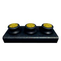
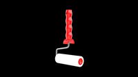
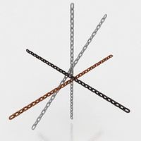
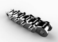
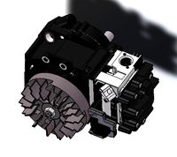
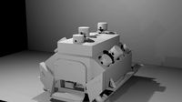
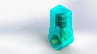
Motor Cycle Engine Internal Setup - Chain Link Roller Style (Inner & Outer Link)
by GrabCAD
Last crawled date: 1 year, 11 months ago
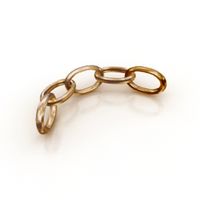
The Final files for this Chain Link roller Style (Inner & Outer Link), enjoy,Solidworks 2014 files with added IGES/STEP,Parasolid,STL & Creo Part files as well.
PLEASE COMMENT & PRESS THE LIKE BUTTON IF YOU DOWNLOAD ( THATS THE HEART SHAPED BUTTON- TOP RIGHT)
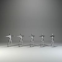
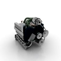
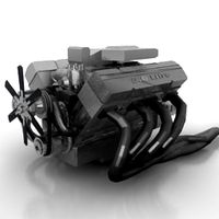
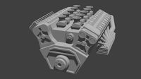
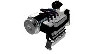
In this Project i have been trying to create a "Motor Cycle Engine" Internal Setup. This model i have learned in one tutorial video.The whole project has been carried out mainly in two software one is PTC CREO & other is Solidworks 2014 for GRAB CAD audience. This will be uploaded part by part as its long one.
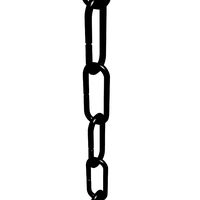
A chain is a series of connected links which are typically made of metal. A chain may consist of two or more links.
Chains are usually made in one of two styles, according to their intended use:
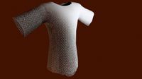
Those designed for lifting, such as when used with a hoist; for pulling; or for securing, such as with a bicycle lock, have links that are torus shaped, which make the chain flexible in two dimensions (The fixed third dimension being a chain's length.)
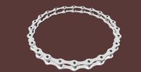
Those designed for transferring power in machines have links designed to mesh with the teeth of the sprockets of the machine, and are flexible in only one dimension. They are known as roller chains, though there are also non-roller chains such as block chain.
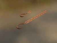
Two distinct chains can be connected using a quick link which resembles a carabiner with a screw close rather than a latch.(Source -Wikipedia)
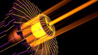
I have uploaded only one fine rendered image with full detailed in Photoshop & Keyshot. I hope you guys like it.
***So stay tuned for more upcoming parts***.
PLEASE COMMENT & PRESS THE LIKE BUTTON IF YOU DOWNLOAD ( THATS THE HEART SHAPED BUTTON- TOP RIGHT)
In this Project i have been trying to create a "Motor Cycle Engine" Internal Setup. This model i have learned in one tutorial video.The whole project has been carried out mainly in two software one is PTC CREO & other is Solidworks 2014 for GRAB CAD audience. This will be uploaded part by part as its long one.
A chain is a series of connected links which are typically made of metal. A chain may consist of two or more links.
Chains are usually made in one of two styles, according to their intended use:
Those designed for lifting, such as when used with a hoist; for pulling; or for securing, such as with a bicycle lock, have links that are torus shaped, which make the chain flexible in two dimensions (The fixed third dimension being a chain's length.)
Those designed for transferring power in machines have links designed to mesh with the teeth of the sprockets of the machine, and are flexible in only one dimension. They are known as roller chains, though there are also non-roller chains such as block chain.
Two distinct chains can be connected using a quick link which resembles a carabiner with a screw close rather than a latch.(Source -Wikipedia)
I have uploaded only one fine rendered image with full detailed in Photoshop & Keyshot. I hope you guys like it.
***So stay tuned for more upcoming parts***.
Similar models
grabcad
free

Chain Assembly
... assembly
grabcad
roller chain assembly in creo 2.0. the assembly is comprised of two chain parts, inner plates and outer links.
grabcad
free

Motor Cycle Engine Internal Setup - Chain Assembly
...dered image with full detailed in photoshop & keyshot. i hope you guys like it.
***so stay tuned for more upcoming parts***.
grabcad
free

Motor Cycle Engine Internal Setup - 1199 Panigale's Superquadro engine -Connecting Rod & Flywheel Assembly
...dered image with full detailed in photoshop & keyshot. i hope you guys like it.
***so stay tuned for more upcoming parts***.
grabcad
free

Motor Cycle Engine Internal Setup - Rocker Shaft
...dered image with full detailed in photoshop & keyshot. i hope you guys like it.
***so stay tuned for more upcoming parts***.
grabcad
free

Motor Cycle Engine Internal Setup - Desmodromic Valve System-Cam Assembly
...dered image with full detailed in photoshop & keyshot. i hope you guys like it.
***so stay tuned for more upcoming parts***.
grabcad
free

Motor Cycle Engine Internal Setup - Desmodromic Valve System-Piston & Cam Shaft Assembly
...dered image with full detailed in photoshop & keyshot. i hope you guys like it.
***so stay tuned for more upcoming parts***.
grabcad
free

Motor Cycle Engine Internal Setup - Desmodromic Valve System - Single Valve & Rocker Assembly
...dered image with full detailed in photoshop & keyshot. i hope you guys like it.
***so stay tuned for more upcoming parts***.
grabcad
free

Motor Cycle Engine Internal Setup - Desmodromic Valve System-Camshaft
...dered image with full detailed in photoshop & keyshot. i hope you guys like it.
***so stay tuned for more upcoming parts***.
grabcad
free

Motor Cycle Engine Internal Setup - 1199 Panigale's Superquadro engine -PRE Assembly
...dered image with full detailed in photoshop & keyshot. i hope you guys like it.
***so stay tuned for more upcoming parts***.
grabcad
free

Motor Cycle Engine Internal Setup - Connecting Rod
...dered image with full detailed in photoshop & keyshot. i hope you guys like it.
***so stay tuned for more upcoming parts***.
Roller
turbosquid
$26
Roller A
...urbosquid
royalty free 3d model roller a for download as fbx on turbosquid: 3d models for games, architecture, videos. (1350603)
turbosquid
$3
Roller
...oyalty free 3d model roller for download as 3ds, max, and obj on turbosquid: 3d models for games, architecture, videos. (1460818)
3ddd
$1
edilkamin roller
...edilkamin roller
3ddd
камин
edilkamin roller 360
3ddd
$1
Roller Blinds
...roller blinds
3ddd
рулонная
roller blinds black out finish
turbosquid
$50
Roller
... roller for download as max, max, c4d, max, max, fbx, and obj on turbosquid: 3d models for games, architecture, videos. (1700762)
3d_export
$10
rollers
...lers
3dexport
this is low-poly model of rollers.<br>model:<br>- low-poly<br>- textured<br>- uv unwrapped
3d_export
$28
Roller 3D Model
...roller 3d model
3dexport
roller construction boss evil
roller 3d model adagio15740837 50561 3dexport
3d_export
$6
hopper roller conveyor
...hopper roller conveyor
3dexport
hopper roller conveyor
3d_export
$12

roller skates
...roller skates
3dexport
3d_ocean
$19
roller skate
...can scanned skates skating sport
3d scan of roller skate. the model has been retopologized and made fully compatible with zbrush.
Outer
turbosquid
$131

Outer Space
...free 3d model ultra realistic outer space for download as max on turbosquid: 3d models for games, architecture, videos. (1677849)
turbosquid
$16

Outer space.jpg
... available on turbo squid, the world's leading provider of digital 3d models for visualization, films, television, and games.
turbosquid
$7

Window outer
... available on turbo squid, the world's leading provider of digital 3d models for visualization, films, television, and games.
3d_export
$65

outer space
...outer space
3dexport
simple rendering of the scene file
turbosquid
$9

Window 3 outer
... available on turbo squid, the world's leading provider of digital 3d models for visualization, films, television, and games.
3d_export
$7

outer-shell-full-face-helmet
...outer-shell-full-face-helmet
3dexport
outer-shell-full-face-helmet
turbosquid
$5

Elbow combined with fastening outer
...model elbow combined with fastening outer for download as max on turbosquid: 3d models for games, architecture, videos. (1558602)
turbosquid
$39

r44 outer high poly
...3d model r44 outer high poly for download as ma, obj, and fbx on turbosquid: 3d models for games, architecture, videos. (1454653)
3d_export
$15

Window outer 3D Model
...model
3dexport
window glass
window outer 3d model download .c4d .max .obj .fbx .ma .lwo .3ds .3dm .stl kirillzlat 113604 3dexport
3d_ocean
$4

Outer Facade Element
...is is a low polygonal model, easy to tile into a bigger structure. - poly count: 382 - formats: max /obj /fbx/3ds/dxf - high d...
Inner
turbosquid
$19

Garden (Inner)
... available on turbo squid, the world's leading provider of digital 3d models for visualization, films, television, and games.
turbosquid
$9

Inner Planets
... available on turbo squid, the world's leading provider of digital 3d models for visualization, films, television, and games.
turbosquid
$1

Inner Beauty
... available on turbo squid, the world's leading provider of digital 3d models for visualization, films, television, and games.
3ddd
free

GRALLEY CENTRO 70 INNER
...ddd
двери , gralley centro inner
дверь hgralley centro inner. мактериалы corona renderer
3d_export
$5

coconut shell inner
...coconut shell inner
3dexport
turbosquid
$150

INNER COURTYARD HOUSE
...yalty free 3d model inner courtyard house for download as skp on turbosquid: 3d models for games, architecture, videos. (1286156)
turbosquid
$5

Tee combined inner
...
royalty free 3d model tee combined inner for download as max on turbosquid: 3d models for games, architecture, videos. (1557785)
turbosquid
$10

inner ship
...
royalty free 3d model nave interior 2020 for download as c4d on turbosquid: 3d models for games, architecture, videos. (1550560)
turbosquid
$7

Inner tee PND fitting
...yalty free 3d model inner tee pnd fitting for download as max on turbosquid: 3d models for games, architecture, videos. (1540255)
design_connected
$10

Inner Nature White Orchid Pot
...inner nature white orchid pot
designconnected
inner nature white orchid pot computer generated 3d model.
Internal
3ddd
$1

Quorum International
... international
3ddd
florence , quorum international
люстра quorum international florence
3d_export
$5

internal door
...internal door
3dexport
internal door
turbosquid
$40

international
... available on turbo squid, the world's leading provider of digital 3d models for visualization, films, television, and games.
3ddd
$1

Lamp International
...ernational
3ddd
lamp international
в файле содержится два светильника от lamp international - люстра арт. 2034/f9 и бра арт. 2026
3ddd
$1

VACCARI INTERNATIONAL
... овальное
производитель vaccari international
серия verona
длина 90, глубина 4,5, высота 70
3ddd
$1

Торшер / Lamp International
...торшер / lamp international
3ddd
lamp international
фабрика lamp international (италия).коллекция siena, арт.3452.
turbosquid
$99

International Soldier
...yalty free 3d model international soldier for download as max on turbosquid: 3d models for games, architecture, videos. (1556764)
turbosquid
$5

Internal door
...id
royalty free 3d model internal door for download as blend on turbosquid: 3d models for games, architecture, videos. (1691264)
3ddd
$1

International Italia 8100
...international italia 8100
3ddd
international italia
люстра lamp international italia 8100 с текстурами и материалами v-ray
turbosquid
$79

International Loadstar
...model international loadstar for download as ma, fbx, and obj on turbosquid: 3d models for games, architecture, videos. (1678922)
Chain
archibase_planet
free
Chain
...chain
archibase planet
chain chain link chain loop
chain n020708 - 3d model (*.gsm+*.3ds) for interior 3d visualization.
3d_export
$5
chain
...chain
3dexport
3d model chain
3d_export
$5
chain
...chain
3dexport
chain. obj,fbx,blend
archibase_planet
free

Chain
...se planet
chain circuit catena
chain - archicad parametrical gdl 3d model (*.gsm). regulation of the length, curvature and angle.
archibase_planet
free
Chain
...n
archibase planet
chain circuit catena
chain - archicad parametrical gdl 3d model(*.gsm). regulation of the length and angle xyz
3d_ocean
$5
Chain
...chain
3docean
3d models chain design elements
3d models, design elements
3d_ocean
$5

Chain
...chain
3docean
3d models chain design elements
3d models, design elements
turbosquid
$10
Chain
...hain
turbosquid
royalty free 3d model chain for download as on turbosquid: 3d models for games, architecture, videos. (1329200)
turbosquid
$9
chain
...hain
turbosquid
royalty free 3d model chain for download as on turbosquid: 3d models for games, architecture, videos. (1549461)
turbosquid
$2
Chain
...hain
turbosquid
royalty free 3d model chain for download as on turbosquid: 3d models for games, architecture, videos. (1148668)
Cycle
turbosquid
$10

cycle
...e
turbosquid
royalty free 3d model cycle for download as dwg on turbosquid: 3d models for games, architecture, videos. (1480437)
turbosquid
$5

Cycles
...s
turbosquid
royalty free 3d model cycles for download as ma on turbosquid: 3d models for games, architecture, videos. (1660228)
turbosquid
$22

cycle
...quid
royalty free 3d model cycle for download as fbx and obj on turbosquid: 3d models for games, architecture, videos. (1667710)
turbosquid
$1

Cycle
...quid
royalty free 3d model cycle for download as jpg and max on turbosquid: 3d models for games, architecture, videos. (1375216)
turbosquid
$45

cycle
...yalty free 3d model cycle for download as obj, fbx, and blend on turbosquid: 3d models for games, architecture, videos. (1419873)
turbosquid
$25

Cycle
...ty free 3d model cycle for download as 3ds, max, obj, and fbx on turbosquid: 3d models for games, architecture, videos. (1432426)
turbosquid
$50

Cycle
... available on turbo squid, the world's leading provider of digital 3d models for visualization, films, television, and games.
turbosquid
$35

Cycle
... available on turbo squid, the world's leading provider of digital 3d models for visualization, films, television, and games.
3d_export
$5

cycle counter
...cycle counter
3dexport
cycle counter
3d_export
$65

Cycling
...cycling
3dexport
simple rendering of the scene file
Motor
archibase_planet
free
Motor
...base planet
motor motor engine engine electric motor
motor wagner n250213 - 3d model (*.gsm+*.3ds) for interior 3d visualization.
archibase_planet
free
Motor
...motor
archibase planet
motor motor engine engine
motor n151112 - 3d model (*.gsm+*.3ds) for interior 3d visualization.
archibase_planet
free
Motor
...motor
archibase planet
motor motor engine engine
motor n150615 - 3d model (*.gsm+*.3ds+*.max) for interior 3d visualization.
turbosquid
$15
Motor
...otor
turbosquid
royalty free 3d model motor for download as on turbosquid: 3d models for games, architecture, videos. (1639404)
3d_ocean
$5
Electric motor
...electric motor
3docean
car electric engine industry motor phase train vehicle
an electric motor enjoy!
3d_ocean
$18
Electric Motor
...electric motor
3docean
electric motor engine machine mover parts
3d model electric motor for hoist crane
turbosquid
$29
Motor
... available on turbo squid, the world's leading provider of digital 3d models for visualization, films, television, and games.
turbosquid
$5
Motor
... available on turbo squid, the world's leading provider of digital 3d models for visualization, films, television, and games.
3d_export
$5
electric motor
...electric motor
3dexport
electric motor use for industrial purposes
3d_export
$5
servo motor
...tor
3dexport
it's a simple part of servo motor 0.75kw for used in machines assembly to show specified motor in own project.
Setup
3d_ocean
$5
Light Setup
...
3docean
light setup lightbox lights render setup
that’s light setup. easy for use. just delete spheres and position your object!
turbosquid
free
Desk setup
...oyalty free 3d model desk setup for download as fbx and blend on turbosquid: 3d models for games, architecture, videos. (1300745)
turbosquid
free
the library.max(setup)
... available on turbo squid, the world's leading provider of digital 3d models for visualization, films, television, and games.
3d_ocean
$5
HDRI Studio Lighting Setup
...ate the hdri into many lighting combinations. increase/decrease intensity. this is the complete lighting setup for vray using ...
3d_ocean
$9
Fireworks - Render Setup
...can be used for any kinds of short movies, or other works. includes a well documentation which includes the steps to change th...
3d_ocean
$5
MentalRay Studio Lighting Setup
...ene which you can change. the colors of the lights are ofcourse tweak-able. this is a basic light setup for you to use for pro...
3d_ocean
$5

Vray scene setup
...studio scene 2. vray setup 3. 2 vray cameras, one of them with dof 4. vray lights 5. vitra panton chair model 6. photoshop fil...
3d_ocean
$15
Render Setups Chair Wall
...render setups chair wall
3docean
chair max render setups vray wall white
render setups chair wall
turbosquid
$25

Interior light setup
...oyalty free 3d model interior light setup for download as c4d on turbosquid: 3d models for games, architecture, videos. (1539984)
turbosquid
$1
basic pc setup
...d
royalty free 3d model basic pc setup for download as blend on turbosquid: 3d models for games, architecture, videos. (1650020)
Style
3ddd
$1

style
...style
3ddd
манекен , одежда
style
3ddd
$1

BM Style
...bm style
3ddd
bm style
кресло bm style с материалами и тестурами
3d_export
$5

style handle
...style handle
3dexport
style handle
3d_export
$6

new style
...new style
3dexport
new style room
turbosquid
$1

style
... available on turbo squid, the world's leading provider of digital 3d models for visualization, films, television, and games.
3d_export
$5

Roman style
...roman style
3dexport
roman style architecture house
3ddd
$1

Ceppi Style
...ceppi style
3ddd
ceppi style
качественная модель классического стола ceppi style с текстурами и материалами v-ray
3ddd
$1

Kolo Style
...kolo style
3ddd
kolo
умывальник kolo style, арт. l21950
3ddd
$1

Banos Style
... style
производитель banos
модель style
в архиве присутствует дополнительная версия с материалами для corona
3ddd
$1

Кухня Free-style
...кухня free-style
3ddd
free-style
кухня free-style
Link
turbosquid
$10

Link
... available on turbo squid, the world's leading provider of digital 3d models for visualization, films, television, and games.
3ddd
$1

Jacuzzi Link
...zzi link , ванна , jacuzzi
ванная jacuzzi link.
3ddd
$1

Nurmela Link
... камыш
модульная мебель nurmela link с декоромhttp://www.nurmela.com/link_en
ширина одной секции 900 мм.
3ddd
$1

Calligaris Link
...garis link.
stackable chair with two-tone seat.
frame: metal matt:
seat: bi-color plastic (abs) matt.
dimensions: 500x530x810mm
design_connected
$18

Link office
...link office
designconnected
lapalma link office computer generated 3d model. designed by welling, hee.
3ddd
$1

CASPRINI LINK
...casprini link
3ddd
casprini
casprini link diritto& intorno
by biagio cisotti/ sandra laube
3ddd
$1

LINK-TABLE
...link-table
3ddd
b&b italia
link-table from b&b;_italia
turbosquid
$3

Bracelet links
...uid
royalty free 3d model bracelet links for download as 3dm on turbosquid: 3d models for games, architecture, videos. (1245412)
turbosquid
$9

link of the bracelet
... model link of the bracelet for download as fbx, obj, and stl on turbosquid: 3d models for games, architecture, videos. (1621965)
3d_ocean
$5

Chain Links
...ogether in blender using rigid bodies. ready to render (r2r) all textures/materials are included files included: .3ds .blend .obj
Engine
3d_export
$5
engine
...engine
3dexport
engine
3d_export
free
Engine
...engine
3dexport
engine
archibase_planet
free
Engine
...engine
archibase planet
motor engine
engine - 3d model for interior 3d visualization.
archibase_planet
free
Engine
...engine
archibase planet
motor engine mover
engine n170708 - 3d model (*.3ds) for interior 3d visualization.
archibase_planet
free
Engine
...engine
archibase planet
engine locomotive train
locomotive - 3d model for interior 3d visualization.
turbosquid
$1
ENGINE
...osquid
royalty free 3d model ic engine for download as sldas on turbosquid: 3d models for games, architecture, videos. (1382781)
3d_export
$5

engine
...engine
3dexport
3d_export
free
engine
...engine
3dexport
turbosquid
$7
Engine
...d model animated engine mograph element3d for download as c4d on turbosquid: 3d models for games, architecture, videos. (1380716)
turbosquid
$1
ENGINE
...y free 3d model engine for download as max, 3ds, stl, and fbx on turbosquid: 3d models for games, architecture, videos. (1673703)