Thingiverse
Mostly Printed CamSlider by dkj4linux
by Thingiverse
Last crawled date: 4 years, 4 months ago
Having built a half-dozen MPCNCs or so, I borrowed from that experience to build a camera slider at the suggestion of my son-in-law... the result, MPCamSlider. I first tried using the entire Z-axis lead-screw assembly from MPCNC... it worked but turned out too slow and noisy for my liking. I converted it over to belt-drive, mixing/mashing up motor- and idler-mounts for the conversion and preserving the conduit spacing from MPCNC's Z-axis assembly. The C-XYZ and C-spacer parts from MPCNC were used then to make a trolley and a custom plate whipped up to add a platform and help tie the trolley roller assemblies together. The overall length of travel can of course be made to suit... I ended up with 32"-33" of linear travel on the prototype.
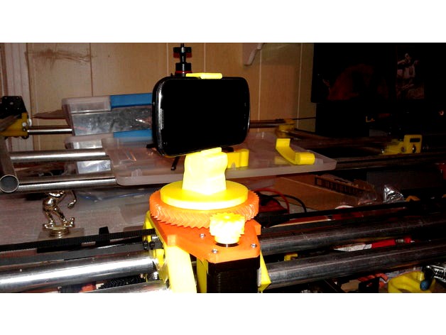
The trolley has a small turntable affixed to the top for a rotation axis. I was originally inspired by the Brainy-bits camera slider tutorials and slider mechanism (https://brainy-bits.com/tutorials/control-2-stepper-motors-using-the-arduino-serial-monitor/)... and was taken by the similarity to Greg's Wade extruder gears for the rotating platform. Only larger! So I found a customizable OpenSCAD design for the herringbone gear set that was almost perfect using the defaults and printed/installed them on the trolley platform. A camera mount base was fashioned to match the hole pattern in the large gear and a previously built cell-phone camera holder affixed to the mounting base.
A common fence slat is used as a mounting base for the entire camera slider... and is needed for strength and to keep the entire mechanism from twisting. A couple of 2" x 4" blocks are cut to fit and the 3/4" EMT conduit fastened with suitable clamps and utility screws.
An Arduino Uno and custom sketch are used to control the camera slider in any of several modes of operation. A4988 stepper motor drivers are used to power the stepper motors on both axis and are set for 1/16 micro-stepping. The belt-drive motor gear is a printed GT2 36-tooth gear with 5mm shaft bore. An IR receiver is also connected to the Arduino... allowing complete control of all CamSlider functions with almost any common TV remote. Start and end setpoints are captured, previewed, user-adjusted for speed in both axis, and then run.
Arduino to A4988 connections are described here (https://www.pololu.com/product/1182) with 1/16 stepping and using the 36-tooth GT2 drive gear. Arduino pins 3,4 connect to X-axis A4988 STEP and DIR pins, respectively. Arduino pins 6,7 connect to Z-axis A4988 STEP and DIR pins, respectively.
The Arduino sketch to control the MPCamSlider has now been made available in Thing Files. The code is fairly heavily commented and instructions are included in the header for identifying codes for a different remote, modding the code, and operating the camera slider.
To see the MPCamSlider in action:
Testing the basic 2-axis camera sliderhttps://www.youtube.com/watch?v=iHw4fDvjaLw
Camera runs with both TRANSLATE and ROTATE axis moving simultaneouslyhttps://www.youtube.com/watch?v=f5eP6A_XUgc&t=31shttps://www.youtube.com/watch?v=fe12ZOdBEGI
Camera run with TRANSLATE-only... translation, no rotationhttps://www.youtube.com/watch?v=KJvaZoEaAXM
Camera run with ROTATE-only... rotation, no translationhttps://www.youtube.com/watch?v=dPlxfGeeGEQ
I have a lengthy -- but incredibly interesting -- thread over in the FliteTest forum that has become quite eclectic in its content. This was a side-project that developed out of nowhere. If interested, the development of the camera slider starts about here...
http://forum.flitetest.com/showthread.php?24251-Cutting-foam-sheets-with-a-needle!&p=315967&viewfull=1#post315967