Thingiverse
Mini SNES Pi Zero w/ Functional Switches by carjo3000
by Thingiverse
Last crawled date: 4 years, 4 months ago
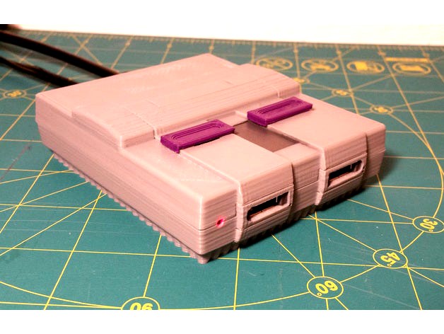
This is my take on a retro gaming console using a Raspberry Pi zero. The SNES case is scaled to 42% the size of the original. To differentiate my design from other SNES Pi cases, I made the top switches functional. The power switch slides up and down to the turn the system on and off, and the reset switch is spring loaded to shutdown and reset the pi. I also changed the power input to a barrel jack, and included a full size HDMI adapter for easier use.
I began designing this around the time Nintendo released the NES classic edition. I was having a really difficult time finding one in stores, so I wanted an alternative to play some retro games while still having that classic console look.
/////////////////////////////////////////////////////////////////////////////////////////////////////////////////////////////////////////////
SNES Pi Main Parts List
1X – Raspberry Pi Zero
1X – Micro SD Card (Enough capacity to load Retro Pi + ROM files)
1X – HDMI Mini adapter - Amazon Link
This is a pretty common adapter which can be purchased from other sources.
1X – 4 port USB hub
I used a USB “Hub man” that I found at Microcenter for $2 but any small USB hub will work.
1X – Perforated Prototype Board (with solder pads)
1X – 5V power supply with a barrel plug
2X – USB gamepads (SNES style obviously…)
I made the mistake of buying a pair of cheap controllers from eBay. You get what you pay for so I recommend spending a little extra for a good set of controllers
Electronics Parts List
The parts I used are fairly common components. You may already have most of them lying around from past projects. If not, you can source them from a local electronics shop or an online source such as Digikey, Mouser, or Ebay.
1X – Barrel jack
1X – Barrel plug (use this if you need to make your own connector)
1X – Right angle tact switch
1X – SPDT slide switch
1X – 3mm red LED
1X – 270 ohm resistor
2X – USB A connectors
3D Printed Parts List
1X – SNES Pi Top
1X – SNES Pi Bottom
1X – PWR Switch
1X – PWR Key
1X – RST Switch
1X – PWR Key
4X – Spacers (use these if your Pi Zero mounting screws are too long)
Hardware List
SAE #4 or 3mm Metric self-tapping screws can be used for this project.
7X – #4-3/8” (M3 – 8mm) screws to secure the Pi, USB board, and switches
4X – #4-5/8” (M3 – 16mm) screws to secure the top and bottom parts of the SNES
1X – Spring
I sourced my spring from a Pilot G2 pen, but nearly any pen spring will work.
RetroPie
You can find full details on how to install and run RetroPie on ypur Raspberry Pi Zero from this Github Link.
Likewise, you can find many useful tutorials from other online sources
Functional Power Switch
Much like the original SNES, the exterior switch is connected to a slide switch on a circuit board inside the case. The power switch for this project is connected in between the power source and the Pi. Turing the switch off will remove power for the Pi. DO NOT use this switch as a primary method of turning off the Pi as it may corrupt the SD card. The best practice is to shutdown the Pi from the RetroPie menu or by executing a shutdown command. After it is properly shutdown, you can then remove power from the Pi.
Functional Reset Switch
I used a pen spring to re-create the same action as the reset switch on the original SNES. When pushed, the 3D printed part actuates a small tact switch that will either shutdown or reset the Pi. The switch will then spring back into place. There are several ways to setup a reset or power switch on your Pi. Any method should work so long as you wire the switches accordingly.
I chose to to make the reset switch on my SNES serve as a shutdown button. Essentially when I press the switch, a script is executed that performs a soft shutdown of the Pi; pressing the button a second time will start the Pi up again. This is accomplished by connecting the switch to GND and GPIO3 on the Pi, and installing a Python script that will execute a shutdown command when the state of the pin is changed. I prefer this method because it allows me to safely shutdown the Pi, which can then be unplugged by turning the power switch off. It's a fairly involved process to setup so I will not go into greater detail beyond that.
If you wish to setup your reset switch this way then I recommend these tutorials. There are also many youtube videos on the subject, just search "retropie reset switch."
Power LED
A red LED will turn on when the system us booted up.The power LED can also be setup in numerous ways. You can connect it directly to your power source, connect it to the Pi, connect it to the USB hub, or even connect it to one of the GPIO pins and run a script to turn it on.
For simplicity, I recommend connecting the LED to the 3.3V pin of the Pi. For this you will also need a 270 ohm resistor. Please see the schematic in the build guide below.