Thingiverse
Mingda D2/D3 Service Bulletin #1 by Pops668
by Thingiverse
Last crawled date: 2 years, 10 months ago
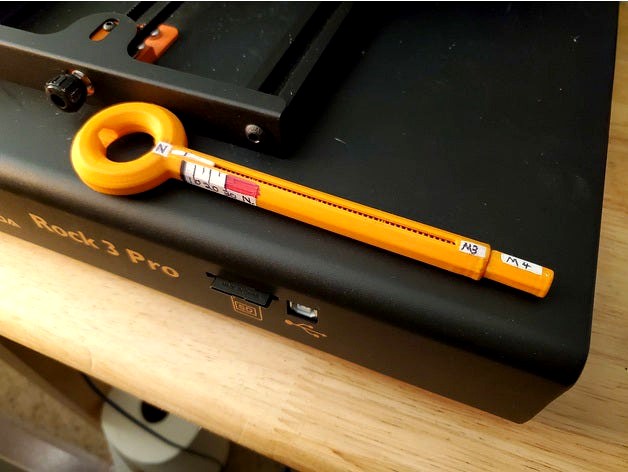
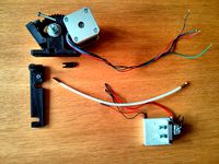
Mingda D2/D3 Field Expedient Repair/modification kit #1.
Contents:
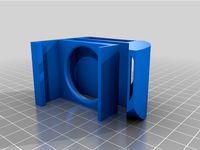
Ah-Tenshunn!™ belt adjustment tool
Body, Indicator, M4/M4 adator, 3x M3 washers, 1x 3mm brass rod, 1x M3 'acorn' nut, 4x harvested Springs
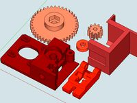
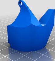
Fair-Trade, Cage-Free Filament Runout Sensor mounting system (not certified Organic)
Pylon, Wheel, Arm, M4 screw, M3 screw, washers and 'acorn' nut, 608 'skate bearing'
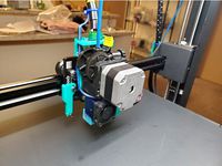
Air-shovel™ parts cooling duct with mounting bracket
Duct, Bracket, M3 screws, washers, nuts
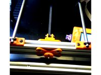
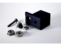
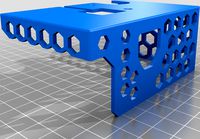
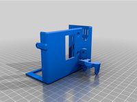
Silent Partner™ Y-axis idler brace, internal
Brace, M5 screws and washers
Lamp hanger brackets to delver the Faithful from darkness...
Left and right hangers...your risk is yours to enjoy...I used 110v 'shop-light', 24V DC LED strip might be a better bet?
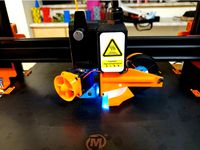
Hot-end and parts cooler fan spinners, optional?
30mm Spinner is slip-on over M3 screw-heads, 5015 Spinner uses M3 screws, washes and nuts for mounting.
Whine-be-Gone™ stepper gaskets and Washers
Gaskets and washers. Simple as a pimple.
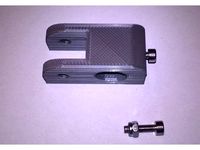
Hobs-Knobs™ strain reliefe whozits for flopsie cable orifices.
Large (Z gantry cable) or small segments (print bed cable), three segments per knob!
(Almost) All parts printed at 0.2 mm layer height, using ColorFabb Dutch Orange or Blue PLA.
Whine-be-Gone™ and Hobs-Kobs™ are printed using ColorFabb VarioShore foaming TPU; 0.25 layers, 30 mm/sec, 245C, 70% flow, no retraction
Printing/ assembly Notes:
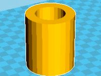
Ah-Tenshunn™ gauge:
1) Indicator has two little internal hooks that line up with coils on the spring. Have to fiddle with it to make it fit right.
Tiny notches on the outside of the Indicator are for pigment/ink/radium glow-paint.
Indicator is PETG, as it is subject to lots of stress and is low-key a safety device.
2) Springs for Ah-Tenshunn!™ tool are harvested from the printing bed.
Don't need springs there, so why not use them for a gauge?
The adjustment knobs support the print-bed on screws, nuts under the Y-axis carrier lock the adjustment in place.
Set and forget.
3) Speaking of accuracy, calibrating the tool uses measured weights.
Your Newton reading is as accurate as your scale and your math...
510 grams = 5 Newtons, 1020 grams = 10 Newtons.
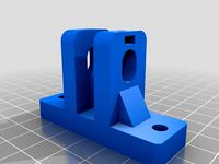
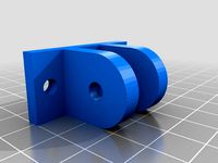
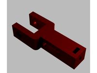
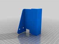
Y-axis brace:
1) Double check spacing of Y-axis idler brace! The curved end must fit snug-close to the inner curve of the chassis and the stepped end clears the cross-brace!
Shims if it short, cut it if it is long.
This part was measured and fitted for a Mingda Rock 3 Pro, likely D2 and D3 use the same cabinet and idler parts...cannot verify it will fit!
Ideal fitment: Y-axis Idler prevents panel from acting as loud-speaker and is fully supported and does not deflect with changes in Y-blyet tenshunn.
Excuse me, Y-belt tension.
Hobs-Knobs™:
1) Print these at 0.6 lines, 0.3 layers, 2 walls, 25% Gyroid infill, 240C @ 70% flow, no retraction. This stuff drools terribly!
Three segments per festering gob to be plugged.
2) Slip each sections 'toe' into the gaping chasm, the last one is a snug 'wiggle fit'.
3) Position the cable to the perfect pose, then secure with ty-rap.
4) Check position after a few prints, the material has an initial 'creep' that you might need to adjust for.
5) These are intended to be snug enough to prevent slipping and rotation!
6) The smaller one is for Heated-bed cable, the larger for Z-gantry cabling.
Whine-be-Gone™ washers and gaskets:
1) Same print setting as the Hobs-Knobs™, except no top or bottom layers, 10% Lines infill, 0.6 line width and 1.8mm walls.
Infill will print 'fluffy' as it is not constrained by neighboring lines and can fully expand.
Walls around holes will print somewhat more densely.
2) You may need to use longer screw to hold the steppers if you use thicker gaskets. Set gasket depth in the slicer by setting a small negative Z displacement!
0.6-0.9mm gaskets are OK for most use, the model uses 1.2mm
3) Washers have a 'bump' on one side; this side goes toward the panel.
Ideally, the panel hole is a little over-sized (3.5-4mm for a 3mm screw) and has a slight chamfer...the TPU squishes into the gap, centering the screw in the hole.
Done right, there should be no eletrical continuity between stepper body and panel. This indicates no metal-to-metal contact to transmit vibration.
Tighten the screws a little at a time to prevent tilting/binding.
Fan Spinners:
OK, these are for fun, but there is one important detail!
1) Hot-end fan is reversed to pull air through heat-sink, rather than blow air at it!
2) Slinging the fan and Spinner down-wind of the Parts Cooler adds to the cooling Mojo.
3) Inlet Spinner for 5015 fan does lower the RPM a bit, this demonstrates less intake turbulance, more air being delivered.
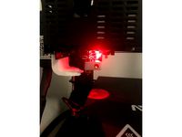
Air-Shovel™:
OK, you got me, t's an air-knife, but that name might be trademarked or something.
1) This part is NOT in final form.
Consider making the outlet ports a little 'taller'.
2) Air delivery is Laser-straight and goes exactly where pointed.
The 'fins' on the top surface are an induction-pump.
Air moving through the ports pulls air between the fins, moving much more air than what comes out the ports!
Bracket holes are a bit over-sized to allow for adjustment.
Air-shovel™ duct is glued onto 5015 fan using E6000
With the Cooler running, air all around printing-plate starts moving from right to left!
It makes its own prevaling winds!
3) 40mm width and spacing from nozzle covers diagonal 'fill' or 'skin' printing.
4) Miniatures are actually over-cooled (PLA printing matte instead of glossy), if that is a thing.
5) Brass nozzle is NOT being actively cooled...did I mention the air-flow was directional like a Laser?
6) Hot-end temps are more stable, not having to fight the Cooling fan.
Full print with 4x4x4 walls/top/bottom and 38% infil came to about 48g in weight.
Glue in lettering and spade. Star may need minor sanding but should push fit into the space tightly and not need anything else to secure it.
Contents:
Ah-Tenshunn!™ belt adjustment tool
Body, Indicator, M4/M4 adator, 3x M3 washers, 1x 3mm brass rod, 1x M3 'acorn' nut, 4x harvested Springs
Fair-Trade, Cage-Free Filament Runout Sensor mounting system (not certified Organic)
Pylon, Wheel, Arm, M4 screw, M3 screw, washers and 'acorn' nut, 608 'skate bearing'
Air-shovel™ parts cooling duct with mounting bracket
Duct, Bracket, M3 screws, washers, nuts
Silent Partner™ Y-axis idler brace, internal
Brace, M5 screws and washers
Lamp hanger brackets to delver the Faithful from darkness...
Left and right hangers...your risk is yours to enjoy...I used 110v 'shop-light', 24V DC LED strip might be a better bet?
Hot-end and parts cooler fan spinners, optional?
30mm Spinner is slip-on over M3 screw-heads, 5015 Spinner uses M3 screws, washes and nuts for mounting.
Whine-be-Gone™ stepper gaskets and Washers
Gaskets and washers. Simple as a pimple.
Hobs-Knobs™ strain reliefe whozits for flopsie cable orifices.
Large (Z gantry cable) or small segments (print bed cable), three segments per knob!
(Almost) All parts printed at 0.2 mm layer height, using ColorFabb Dutch Orange or Blue PLA.
Whine-be-Gone™ and Hobs-Kobs™ are printed using ColorFabb VarioShore foaming TPU; 0.25 layers, 30 mm/sec, 245C, 70% flow, no retraction
Printing/ assembly Notes:
Ah-Tenshunn™ gauge:
1) Indicator has two little internal hooks that line up with coils on the spring. Have to fiddle with it to make it fit right.
Tiny notches on the outside of the Indicator are for pigment/ink/radium glow-paint.
Indicator is PETG, as it is subject to lots of stress and is low-key a safety device.
2) Springs for Ah-Tenshunn!™ tool are harvested from the printing bed.
Don't need springs there, so why not use them for a gauge?
The adjustment knobs support the print-bed on screws, nuts under the Y-axis carrier lock the adjustment in place.
Set and forget.
3) Speaking of accuracy, calibrating the tool uses measured weights.
Your Newton reading is as accurate as your scale and your math...
510 grams = 5 Newtons, 1020 grams = 10 Newtons.
Y-axis brace:
1) Double check spacing of Y-axis idler brace! The curved end must fit snug-close to the inner curve of the chassis and the stepped end clears the cross-brace!
Shims if it short, cut it if it is long.
This part was measured and fitted for a Mingda Rock 3 Pro, likely D2 and D3 use the same cabinet and idler parts...cannot verify it will fit!
Ideal fitment: Y-axis Idler prevents panel from acting as loud-speaker and is fully supported and does not deflect with changes in Y-blyet tenshunn.
Excuse me, Y-belt tension.
Hobs-Knobs™:
1) Print these at 0.6 lines, 0.3 layers, 2 walls, 25% Gyroid infill, 240C @ 70% flow, no retraction. This stuff drools terribly!
Three segments per festering gob to be plugged.
2) Slip each sections 'toe' into the gaping chasm, the last one is a snug 'wiggle fit'.
3) Position the cable to the perfect pose, then secure with ty-rap.
4) Check position after a few prints, the material has an initial 'creep' that you might need to adjust for.
5) These are intended to be snug enough to prevent slipping and rotation!
6) The smaller one is for Heated-bed cable, the larger for Z-gantry cabling.
Whine-be-Gone™ washers and gaskets:
1) Same print setting as the Hobs-Knobs™, except no top or bottom layers, 10% Lines infill, 0.6 line width and 1.8mm walls.
Infill will print 'fluffy' as it is not constrained by neighboring lines and can fully expand.
Walls around holes will print somewhat more densely.
2) You may need to use longer screw to hold the steppers if you use thicker gaskets. Set gasket depth in the slicer by setting a small negative Z displacement!
0.6-0.9mm gaskets are OK for most use, the model uses 1.2mm
3) Washers have a 'bump' on one side; this side goes toward the panel.
Ideally, the panel hole is a little over-sized (3.5-4mm for a 3mm screw) and has a slight chamfer...the TPU squishes into the gap, centering the screw in the hole.
Done right, there should be no eletrical continuity between stepper body and panel. This indicates no metal-to-metal contact to transmit vibration.
Tighten the screws a little at a time to prevent tilting/binding.
Fan Spinners:
OK, these are for fun, but there is one important detail!
1) Hot-end fan is reversed to pull air through heat-sink, rather than blow air at it!
2) Slinging the fan and Spinner down-wind of the Parts Cooler adds to the cooling Mojo.
3) Inlet Spinner for 5015 fan does lower the RPM a bit, this demonstrates less intake turbulance, more air being delivered.
Air-Shovel™:
OK, you got me, t's an air-knife, but that name might be trademarked or something.
1) This part is NOT in final form.
Consider making the outlet ports a little 'taller'.
2) Air delivery is Laser-straight and goes exactly where pointed.
The 'fins' on the top surface are an induction-pump.
Air moving through the ports pulls air between the fins, moving much more air than what comes out the ports!
Bracket holes are a bit over-sized to allow for adjustment.
Air-shovel™ duct is glued onto 5015 fan using E6000
With the Cooler running, air all around printing-plate starts moving from right to left!
It makes its own prevaling winds!
3) 40mm width and spacing from nozzle covers diagonal 'fill' or 'skin' printing.
4) Miniatures are actually over-cooled (PLA printing matte instead of glossy), if that is a thing.
5) Brass nozzle is NOT being actively cooled...did I mention the air-flow was directional like a Laser?
6) Hot-end temps are more stable, not having to fight the Cooling fan.
Full print with 4x4x4 walls/top/bottom and 38% infil came to about 48g in weight.
Glue in lettering and spade. Star may need minor sanding but should push fit into the space tightly and not need anything else to secure it.
Similar models
thingiverse
free
Y belt tensioner for 2020 and 2040 aluminum extrusion by FFranzmann
...f prusa and haribo mod designs
you need to drill a hole for the m4 in your extrusion
added a version for 2020 although untested.
thingiverse
free
Hinged Wade's Geared by stratop80
...s. m4x50mm screws, 1pcs. compression spring, 1pcs. m4 nut, and 1pcs m4 fender washers for hinged idler.
hope it results useful!
thingiverse
free
Prusa_I3_MK2_Y_Belt_Idler_Tensioner by Andison
... and washers.
the idler is designed in a way that it does not impact heat bed movement or minimize printing area respectively.
thingiverse
free
Hictop 3dp11 Adjustable Y Idler Mount by SaberShip
...rts:
x1 stock 608zz idler bearing
x1 stock m3 bolt and nut
x2 stock m5 bolts
x2 stock m5 t-slot nuts
x2 m3 x 10 screws
x2 m3 nuts
thingiverse
free
Belt Idler for Y Axis - M5 idler size (2020 Mount) by eldor_x
...ler from the original y idler using an m5 thread to screw through it.
you will need 2x m4 8mm screws and 2x m4 t-nut to mount it
thingiverse
free
Tronxy X3 Belt Idler by 1sPiRe
...d° - gearbest°
tronxy x3° from gearbest°
12% off coupon from gearbest : gbte
part of my tronxy x3 upgrades collection
° affiliate
thingiverse
free
Folger FT-5 Idler Supports by Sky120
...3 lock-nut are required for each pulley. the offset supports are for the y axis and the equal height supports are for the x axis.
thingiverse
free
Hobbed Bolt Bowden Drive by tech3d
...
nb: i've added a modified huxley mount. i haven't tested this as i don't have a frame. let me know if you try it. :)
thingiverse
free
Wilson 2. Heavy Duty Y Tensioner. by lowfat
... to heat up the m3 nut for it to slide down the hole.
an m4 x 25mm and m4 nut is required to secure the tensioner to the y idler.
thingiverse
free
Mingda d2 & d3 fan duct by Viktoras321
...mingda d2 & d3 fan duct by viktoras321
thingiverse
get better cooling and better air flow with this fan duct
Pops668
thingiverse
free
Ruby Laser Rod burnisher by Pops668
...ue it in, but why not?
printed on an anycubic mega x using filaments.ca silver eco-tough pla.
not much more than that for now...
thingiverse
free
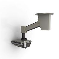
MINGDA Rock 3 Pro Parts Cooler by Pops668
...t-end nozzle is touching the build-plate!
7) it is whisper quiet when at 100% cooling effort! you hardly know the thing is on!!!
thingiverse
free

Ah TENSHUN! belt tension guage by Pops668
...i didn't need them, didn't model them, so i am not including them!
can't think of anything else, signing off!
pops668
thingiverse
free
Anycubic Mega X Direct Drive conversion kit by Pops668
...ad to set x width to 290mm; i will make a rear-mount cooling fan soon!
not ideal, but the difference in print quality is amazing!
Mingda
thingiverse
free
Mingda D2 Hot end Cover by OctagonalVector
...mingda d2 hot end cover by octagonalvector
thingiverse
mingda d2 hot end cover
thingiverse
free
fan duct for Mingda MD-6L by mdatom
...fan duct for mingda md-6l by mdatom
thingiverse
this is a ring fan duct for mingda md-6l.
thingiverse
free
Mingda Filament Spool Collar by andyhill
...ool collar by andyhill
thingiverse
the mingda glitar 6s 3d printer filament spool holder requires this collar to spool corectly.
thingiverse
free
Mingda D2 Raspberry Bracket by El_A_lex
...g raspberry on the mingda d2.
i took the unused screwholes on the right side of the printer and designed a bracket fitting there.
thingiverse
free
Mingda d2 d3 Druckbett Kabel Entlastung /Halter by BadMansGeheimLabor3D
...mingda d2 d3 druckbett kabel entlastung /halter by badmansgeheimlabor3d
thingiverse
mingda d2 d3 kabelbruch stop
thingiverse
free
Mingda X-Axis Tensionner by tilange
...mingda x-axis tensionner by tilange
thingiverse
2 or 4 m3 bolt needed .. !
thingiverse
free
Mingda D2 fan for 5015 by matatt
...mingda d2 fan for 5015 by matatt
thingiverse
fan 5015 24v
infill 40%
petg
no support
thingiverse
free
Mingda D-2 Extruder cover with cable Chain adapter by fluxcore
...d-2 extruder cover with cable chain adapter by fluxcore
thingiverse
mingda d-2 extruder cover with integrated cablechain adapter
thingiverse
free

Mingda D2 Cura Profile (PLA) + Printer Settings + StartEnd Gcode by fabiofilippini
... + startend gcode by fabiofilippini
thingiverse
some mods i designed for the mingda d2:https://www.thingiverse.com/thing:4659128
thingiverse
free
Mingda D2 Fan Assembly Housing by Kevins3DCreations
...upports are needed.
overview video can be found here - https://youtu.be/ywhupdg_9si
twitter @k3dc_
instagram at kevins3dcreations
Bulletin
3d_ocean
$5
Bulletin Board
...extured easy if you like ) fits for any urban enviroment, such as interior, office levels or whatever you like. low poly! 136 ...
turbosquid
$22
Old Bulletin Board
... available on turbo squid, the world's leading provider of digital 3d models for visualization, films, television, and games.
3d_ocean
$10

3D Cork Bulletin Board
...essential details to used in your next project. it has a wood frame featuring 4 separate edges like a real board would, instea...
3d_export
$9

sci-fi bulletin board from rick and morty
...s such texture maps as normal (opengl) bace color roughness metalic height emissive model have verts-1.280 faces-2.342 tris-2.342
archibase_planet
free

Billboard
...billboard archibase planet advertisement hoarding billboard bulletin board billboard n220210 - 3d model (*.gsm+*.3ds) for exterior...
archive3d
free

Billboard 3D Model
...billboard 3d model archive3d advertisement hoarding billboard bulletin board billboard n220210 - 3d model (*.gsm+*.3ds) for exterior...
archibase_planet
free

Board
...board archibase planet board information board bulletin board board information n310813 - 3d model (*.gsm+*.3ds) for...
archive3d
free

Board 3D Model
...board 3d model archive3d board information board bulletin board board information n310813 - 3d model (*.gsm+*.3ds) for...
3d_export
$10

Office Interior Props 3D Model
...3dexport office props game enviroment chair folding bilboard whitetable bulletin table noticeboard pin-up board interior office interior props 3d...
3d_ocean
$4
Push Pin Pack
...push pin pack 3docean board bulletin corkboard high metal office pin plastic push resolution schedule...
D3
turbosquid
$60
Albatros D3
...osquid
royalty free 3d model albatros d3 for download as 3ds on turbosquid: 3d models for games, architecture, videos. (1206830)
turbosquid
$110

Albatros D3
... available on turbo squid, the world's leading provider of digital 3d models for visualization, films, television, and games.
turbosquid
$8
D3 Bookcase
...d3 bookcase for download as ma, 3ds, max, obj, fbx, and blend on turbosquid: 3d models for games, architecture, videos. (1339364)
3ddd
free
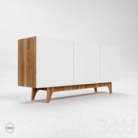
ODESD2 D3
...м шпонированная дубом фанера, мдф, фурнитура blum
размеры: ширина: 425мм, длина: 1200мм, высота: 800ммhttp://odesd2.com
3d_export
$5

Buggy d3 3D Model
...buggy d3 3d model
3dexport
buggy
buggy d3 3d model 1201314354 62357 3dexport
turbosquid
$20
Bowers & Wilkins HTM2 D3 Rosenut on FS HTM D3 Black
... available on turbo squid, the world's leading provider of digital 3d models for visualization, films, television, and games.
turbosquid
$100

Motorola RAZR D3
... available on turbo squid, the world's leading provider of digital 3d models for visualization, films, television, and games.
turbosquid
$20
Bowers & Wilkins HTM2 D3 Satin White on FS HTM D3 Silver
... available on turbo squid, the world's leading provider of digital 3d models for visualization, films, television, and games.
turbosquid
$20
Bowers & Wilkins HTM2 D3 Gloss Black on FS HTM D3 Black
... available on turbo squid, the world's leading provider of digital 3d models for visualization, films, television, and games.
turbosquid
$99
Osiris D3 Skate shoe
...ree 3d model osiris d3 skate shoe for download as obj and fbx on turbosquid: 3d models for games, architecture, videos. (1403308)
D2
3d_export
$17

Albatros d2
...albatros d2
3dexport
albatros d2
3ddd
$1
Hulsta D2
...hulsta d2
3ddd
hulsta
кресло hulsta d2
3ddd
$1
Albotros D2
...albotros d2
3ddd
самолет
модель самолета первой мировой albotros d2 материалы+текстуры
3dsmax2009 vray-1.50
turbosquid
$15
Cowon D2
... available on turbo squid, the world's leading provider of digital 3d models for visualization, films, television, and games.
turbosquid
$5
d2.max
... available on turbo squid, the world's leading provider of digital 3d models for visualization, films, television, and games.
3ddd
$1
ODESD2 D2
...м шпонированная дубом фанера, мдф, фурнитура blum
размеры: ширина: 425мм, длина: 1800мм, высота: 800ммhttp://odesd2.com
turbosquid
$26
Ship screw D2
...quid
royalty free 3d model ship screw d2 for download as fbx on turbosquid: 3d models for games, architecture, videos. (1479420)
turbosquid
$19

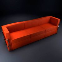
Sofa Tuxedo D2
...uid
royalty free 3d model sofa tuxedo d2 for download as max on turbosquid: 3d models for games, architecture, videos. (1711805)
turbosquid
$19

Sofa Tuxedo D2
...uid
royalty free 3d model sofa tuxedo d2 for download as max on turbosquid: 3d models for games, architecture, videos. (1711800)
3ddd
free
Vistosi | Cocumis SP G D2
...vistosi | cocumis sp g d2
3ddd
vistosi
cocumis sp g d2
Service
archibase_planet
free
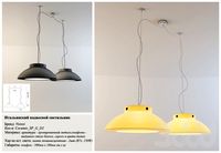
Service
...service
archibase planet
service pendant hospital equipment
surgical service pendant - 3d model for interior 3d visualization.
3ddd
free

Service
...service
3ddd
сервиз
3ds max 2010.v-ray 2.40.03.file formats fbx,obj. service
3d_export
$5
Service
...service
3dexport
made in blender
3ddd
$1

Service
...service
3ddd
сервиз , посуда
;)
archibase_planet
free

Tea-service
...archibase planet
tea-service cover place setting kitchen ware
tea-service - 3d model (*.gsm+*.3ds) for interior 3d visualization.
3d_export
$7

bedding service
...bedding service
3dexport
the bedding service from the is the embodiment of absolute comfort and impeccable modern style.
3ddd
$1

Service
...ice
3ddd
сервиз , посуда
сделано по фото, размеры могла немного не соблюсти)) извините))
turbosquid
$99
Rail services
...quid
royalty free 3d model rail services for download as fbx on turbosquid: 3d models for games, architecture, videos. (1147245)
turbosquid
$20
Service Cart
...squid
royalty free 3d model service cart for download as obj on turbosquid: 3d models for games, architecture, videos. (1294512)
turbosquid
$6

Service station
...id
royalty free 3d model service station for download as fbx on turbosquid: 3d models for games, architecture, videos. (1708506)
1
turbosquid
$69

armchairs(1)(1)
... available on turbo squid, the world's leading provider of digital 3d models for visualization, films, television, and games.
turbosquid
$15
ring 1+1
... available on turbo squid, the world's leading provider of digital 3d models for visualization, films, television, and games.
turbosquid
$10
chair(1)(1)
... available on turbo squid, the world's leading provider of digital 3d models for visualization, films, television, and games.
turbosquid
$8

Chair(1)(1)
... available on turbo squid, the world's leading provider of digital 3d models for visualization, films, television, and games.
turbosquid
$2

RING 1(1)
... available on turbo squid, the world's leading provider of digital 3d models for visualization, films, television, and games.
turbosquid
$1

Table 1(1)
... available on turbo squid, the world's leading provider of digital 3d models for visualization, films, television, and games.
turbosquid
$1
house 1(1)
... available on turbo squid, the world's leading provider of digital 3d models for visualization, films, television, and games.
turbosquid
$59

Formula 1(1)
...lty free 3d model formula 1 for download as max, fbx, and obj on turbosquid: 3d models for games, architecture, videos. (1567088)
design_connected
$11
No 1
...no 1
designconnected
sibast no 1 computer generated 3d model. designed by sibast, helge.
turbosquid
$2
desert house(1)(1)
...3d model desert house(1)(1) for download as 3ds, max, and obj on turbosquid: 3d models for games, architecture, videos. (1055095)