GrabCAD

Mecanum Wheel Type-B__Revision B3.2
by GrabCAD
Last crawled date: 1 year, 11 months ago
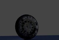
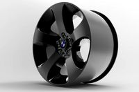
Mecanum wheel type b revision B-3.2
Formats Notes:
asm format = Solid Edge ST5 (GrabCAD insist it's ST4).
x_t format = Parasolid text file.
x_b format = Parasolid binary transmit file.
JT format = JT open CAD format.
A real concept model of a Mecanum wheel with rollers breaking system.
Though incredibly versatile, the standard Mecanum wheel has an unfortunate side effect which reduce its efficiency considerably. It's wide range of mobility is due to the fact that the peripheral rollers translate a portion of the driving motor force into a force perpendicular or at an angle to that produce by the driving motor. This means that large portion of the force in one direction is lost though the translation into a resulting force by the rollers. As an extreme example of this inefficiency, when the platform travel diagonally, only a front and rear opposing wheels are spinning whilst the rollers on the other two wheels cause direct drag that the motors must fight against. (Australasian conference on robotics 27-29 November 2002)
This problem can be solved in a few ways:
1. Controlling the rollers spins (Mecanum wheel type B)
2. Rotating the rollers assembly arm (Mecanum wheel type R)
3. Rotating the spoke (rollers assembly) & control the spinning speed of the rollers (Type BR)
Rotating the main spoke also solve one big headache that is caused by damaged or uneven rollers (erosion damage), however you need to know how much to rotate the spoke & to what direction (CW or CCW). You also need to know when to rotate the spoke. Of course the same is true regarding braking or slowing the rollers spin.
Any change to rollers angle &/or speed is effecting the main vector of the wheel assembly (i.e the direction of the wheel movement), called “off course vector”. There are some other variables like ground condition, speed, load, contact angle etc that will all combine in the shape of OC Vector.
That pesky OCV is the main reason for the complexity of this system. Gyroscopic servo controlling spinning mechanical parts under load… well designing a complex system bottom-up style is what Spaceclaim do best as you can see with your own eyes.
About this specific model:
This one of the early revisions that uses hydro restriction valve as means to control the rollers spin. This system while relatively simple & elegant found to be problematic & did not pass the mechanical simulation stage. It is however the real model with only a few of the system missing. Sensors wiring harness, hub planetary reduction gear & the restriction valve harness & Spokes rotation systems & gear to name a few.
Even so you got about 1800 parts & if you dig a bit into the design you will understand planty.
Hope you like it :)
Nesher Amir
Similar models
grabcad
free

Mecanum Wheel Type-B Revision-A1
...orking will put the platform out of control if the conditions are hard enough.
5. expensive to produce & hard to maintenance
grabcad
free

Mecanum Wheel
...n without modifying the wheels themselves. it is ideal for small spaces.
here is solidworks model of a mecanum wheel made by me.
grabcad
free

MECANUM WHEEL
...gle to the axis of rotation of the wheel. this makes the wheel exert force in diagonal direction when moving forward of backward.
grabcad
free

mecanum wheel in solidworks
...mobile robot[4] (pictured) or a wheelchair with mecanum wheels (similar to that pictured).[5], with an alternating with left- and...
grabcad
free

Mecanum Wheels Using Solidworks
...ngle to the axis of rotation of the wheel. this makes the wheel exert force in diagonal direction when moving forward of backward
grabcad
free

Mecanum Wheel Robot
...gle to the axis of rotation of the wheel. this makes the wheel exert force in diagonal direction when moving forward of backward.
3dwarehouse
free

Mecanum Drive Base
...ement from the rollers. made for ps2 controller. #base #chassis #drive #mecanum #norviewsveteran #sketchyphysics #sketchyphysics3
grabcad
free

Mecanum Wheel
...erpendicular to the roller axle, which can be vectored into a longitudinal and a transverse component in relation to the vehicle.
grabcad
free

Mecanum Wheel Super Traction
...ess the 60 hours from idea to screen pics... spaceclaim i love you :)
btw sorry but there is no damn iphone in this model \o/ ;)
grabcad
free

Mecanum Wheel
...erpendicular to the roller axle, which can be vectored into a longitudinal and a transverse component in relation to the vehicle.
Mecanum
thingiverse
free

Mecanum 50mm by RendiPambudi
...mecanum 50mm by rendipambudi
thingiverse
this is a mecanum wheel for omnidirectional mobile robot. hope you enjoy it
thingiverse
free

Arduino Mecanum Box
...ity.i share you and free
anyway ,this is box for mecanum carhttps://howtomechatronics.com/projects/arduino-mecanum-wheels-robot/
thingiverse
free

wheel mecanum by Joakim
...wheel mecanum by joakim
thingiverse
this is has many ancestors....http://www.thingiverse.com/search?q=mecanum&sa=search
thingiverse
free

Mecanum wheels robot by acicuecalo
...mecanum wheels robot by acicuecalo
thingiverse
omnidirectional mobile robot with mecanum wheels.
thingiverse
free

Mecanum Wheel with separate hub
...mecanum wheel with separate hub
thingiverse
mecanum wheel with separate hub, made for 5 mm shaft.
thingiverse
free

ftc mecanum wheel by cpodbob
...ftc mecanum wheel by cpodbob
thingiverse
i was wondering if i could make a set of ftc legal mecanum wheel
thingiverse
free

MECANUM WHEELS CAR
...mecanum wheels car
thingiverse
follow me on youtube!
thingiverse
free

Lego Mecanum Wheel by maxchambers3
...axchambers3
thingiverse
this is a custom made 3d printed mecanum wheel designed to work with lego power functions, nxt, and ev3.
thingiverse
free

FRC 2020 Mecanum Wheels
... infinite recharge,
mecanum wheels for ball intake.
https://twitter.com/istiklal7481
https://www.instagram.com/istiklalrobotics/
thingiverse
free

Nema 17 Mecanum
...nema 17 mecanum
thingiverse
making something like robomaster s1
B3
3ddd
$1

Yamaha B3 Upright Piano
...right , piano , пианино
yamaha b3 upright piano
turbosquid
$25

b3.c4d
... available on turbo squid, the world's leading provider of digital 3d models for visualization, films, television, and games.
turbosquid
$26

Ship screw B3
...quid
royalty free 3d model ship screw b3 for download as fbx on turbosquid: 3d models for games, architecture, videos. (1451408)
3d_export
$5

wheel volkswagen passat b3 1987
...wheel volkswagen passat b3 1987
3dexport
wheel volkswagen passat b3 1987
3d_ocean
$55

Volkswagen Passat B3
...r formats : -.blend, rendered with cycles, as seen in the images; -.obj, with materials and textures applied; -.dae, with mate...
3d_export
$15

VW Passat B3 tuned 3D Model
...vw passat b3 tuned 3d model
3dexport
vw passat b3 tuning car transport
vw passat b3 tuned 3d model skull 180 3dexport
3d_export
$50

Volkswagen Passat B3 3D Model
...edan modern fancy germany black 3d model 3ds obj b3 1988 1989 1990 1991
volkswagen passat b3 3d model dragosburian 84408 3dexport
turbosquid
$10

Calculator Electronica B3-26
...electronica b3-26 for download as max, 3ds, fbx, obj, and stl on turbosquid: 3d models for games, architecture, videos. (1519557)
cg_studio
$15

Macel Breuer B3 chair3d model
...3 chair3d model
cgstudio
.lwo - macel breuer b3 chair 3d model, royalty free license available, instant download after purchase.
turbosquid
$15

Niacinamide Vitamin B3 Molecular C6H6N2O
...lar model c6h6n2o for download as max, max, fbx, 3ds, and obj on turbosquid: 3d models for games, architecture, videos. (1548348)
Revision
turbosquid
$40

counter display revised
... available on turbo squid, the world's leading provider of digital 3d models for visualization, films, television, and games.
turbosquid
$30

Cascade sewage revision shaft crosscut
... available on turbo squid, the world's leading provider of digital 3d models for visualization, films, television, and games.
3d_export
$10

room interior design model 001
...not be afraid, you can ask me for the revision by contact me with email, i will do it...
3d_export
$15

engineering drone scifi
...loads, fly, shoot, drill, mine.<br>fully rigged. animated fly (need revision. modelled and rigged in blender. textured in substance painter.<br>textures:...
cg_studio
$30

Apple iphone 4 Cell Phone LAST revision3d model
...4d .wrl .wrz - apple iphone 4 cell phone last revision 3d model, royalty free license available, instant download after purchase.
3d_export
$7

ficus alii plant
...2016.09.06 16:32<br>formfactor: circle<br>style: modern<br>material: metal organics<br>color:<br>description<br>ficus plants ,,, small revision in modeling ,,, max2015,2012 & fbx ,,...
3d_export
$10

antonio lupi design timbro
...ollection. timbro is available top or wall mount and freestanding also. timbro tops are made of polished<br>chrome brass.
3d_export
free

bed - sample
...game and animation.<br>- custom texture with 4k resolution png format.<br>revision (24/12/2020)<br>- reupload with new fbx format.<br>- edge loops added...
3d_export
$60

mitsubishi galant 1996 - 1999 -- 8th generation -- sedan
...ented as separate objects. if you have any difficulties or need a model in a certain format, write and we will solve the problem.
3d_export
$27

the latest automatic n95 mask machine production line drawings
...trasonic heat sealing system. the whole machine has stable performance, high production efficiency and high degree of automation.
B
3ddd
$1
B&B
...b&b
3ddd
b&b italia
statue b&b italy
3ddd
$1
B&B Italia
...b&b italia
3ddd
b&b italia
b&b; italia
3ddd
$1

b&b italia
...b&b italia
3ddd
b&b italia
b&b; italia
3ddd
$1

B&B LAZY
...b&b lazy
3ddd
b&b italia
b&b; lazy
3ddd
$1
B&B Italy
...b&b italy
3ddd
b&b italia
диван b&b; italy
3ddd
$1

b&b RAY
...b&b ray
3ddd
b&b italia , угловой
диван b&b; ray
3ddd
$1
B&B Beverly
... b&b italia , beverly
cтул beverly от b&b.; текстуры в архиве
3ddd
$1

B&B ITALIA
...lia , журнальный , круглый
стол b&b; italia
3ddd
$1
шезлонг B&B
...шезлонг b&b
3ddd
b&b italia , шезлонг
шезлонг b&b; terminal 1
3ddd
$1

B&B J.J
...b&b j.j
3ddd
b&b italia , журнальный
b&b;
j.j
45x40x49 cm
Wheel
archibase_planet
free
Wheel
...l steering control steering wheel
wheel ship steering wheel n060215 - 3d model (*.gsm+*.3ds+*.max) for exterior 3d visualization.
3d_ocean
$14
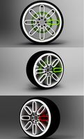
Wheel
...wheel
3docean
car rim car wheel rim wheel
high poly car wheel design. 16,840 polys
3d_export
free
wheel
...wheel
3dexport
wheel
3d_export
free
wheel
...wheel
3dexport
wheel
3d_export
free
Wheel
...wheel
3dexport
wheel
3d_export
$5

wheel
...wheel
3dexport
wheel for car.
3d_export
$5
wheel
...wheel
3dexport
car wheel
3d_export
$5
wheel
...wheel
3dexport
car wheel
3d_export
$5
wheel
...wheel
3dexport
car wheel
3d_export
$5
wheel
...wheel
3dexport
car wheel
Type
3d_export
$5

s type
...s type
3dexport
s type formats max 3ds obj stl
3d_export
$5

l-type conveyor
...l-type conveyor
3dexport
l-type conveyor
3d_export
$5

volkswagen type 2
...volkswagen type 2
3dexport
volkswagen type 2
turbosquid
$150

RBC types
...osquid
royalty free 3d model rbc types for download as blend on turbosquid: 3d models for games, architecture, videos. (1343563)
turbosquid
$1

B-Type
...urbosquid
royalty free 3d model b-type for download as blend on turbosquid: 3d models for games, architecture, videos. (1609608)
3ddd
$1

shoes type A
...shoes type a
3ddd
туфли
shoes
turbosquid
$39

R-type
...oyalty free 3d model r-type for download as max, obj, and fbx on turbosquid: 3d models for games, architecture, videos. (1303675)
turbosquid
$5

melon type
...ee 3d model melon galia type for download as ma, fbx, and obj on turbosquid: 3d models for games, architecture, videos. (1557188)
3d_export
free
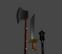
three different type
...three different type
3dexport
three different type: mace, axe, sword
turbosquid
$49

Types of Placentation
... available on turbo squid, the world's leading provider of digital 3d models for visualization, films, television, and games.
2
design_connected
$11
No 2
...no 2
designconnected
sibast no 2 computer generated 3d model. designed by sibast, helge.
turbosquid
$6
Cliff Rock 2-2
...uid
royalty free 3d model cliff rock 2-2 for download as obj on turbosquid: 3d models for games, architecture, videos. (1619161)
turbosquid
$29

Book variation 2 2
...3d model book variation 2 2 for download as max, obj, and fbx on turbosquid: 3d models for games, architecture, videos. (1366868)
turbosquid
$22
Classic baluster (2) (2)
...assic baluster (2) (2) for download as max, obj, fbx, and stl on turbosquid: 3d models for games, architecture, videos. (1483789)
turbosquid
$99

Smilodon 2 Pose 2
... available on turbo squid, the world's leading provider of digital 3d models for visualization, films, television, and games.
turbosquid
$20
Barrel Barricade 2-2
... available on turbo squid, the world's leading provider of digital 3d models for visualization, films, television, and games.
turbosquid
$6
Wall Trophy (2) (2)
... available on turbo squid, the world's leading provider of digital 3d models for visualization, films, television, and games.
turbosquid
free
Tire label 2 of 2
... available on turbo squid, the world's leading provider of digital 3d models for visualization, films, television, and games.
3ddd
$1

Кровать, 2 тумбочки, 2 светильника
...кровать, 2 тумбочки, 2 светильника
3ddd
кровать, 2 тумбочки, 2 светильника
нормальное качество
формат 3ds max
без текстур
3ddd
free

Кровать, 2 тумбочки, 2 светильника
...кровать, 2 тумбочки, 2 светильника
3ddd
кровать, 2 тумбочки, 2 светильника
нормальное качество
формат 3ds max
без текстур