GrabCAD
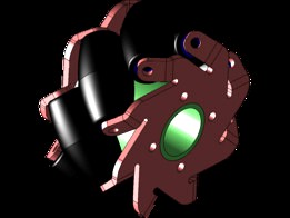
mecanum wheel in solidworks
by GrabCAD
Last crawled date: 1 year, 10 months ago
The Mecanum wheel is based on a tireless wheel, with a series of rubberized external rollers obliquely attached to the whole circumference of its rim. These rollers typically each have an axis of rotation at 45° to the wheel plane and at 45° to the axle line.[3] Each Mecanum wheel is an independent non-steering drive wheel with its own powertrain, and when spinning generates a propelling force perpendicular to the roller axle, which can be vectored into a longitudinal and a transverse component in relation to the vehicle.
The typical Mecanum design is the four-wheel configuration as demonstrated by one of the URANUS omni-directional mobile robot[4] (pictured) or a wheelchair with Mecanum wheels (similar to that pictured).[5], with an alternating with left- and right-handed rollers whose axles at the top of the wheel are parallel to the diagonal of the vehicle frame (and hence perpendicular to the diagonal when at where the bottom of the wheel contacts the ground). In such a way, each wheel will generate a thrust roughly parallel to the corresponding frame diagonal. By varying the rotational speed and direction of each wheel, the summation of the force vectors from each of the wheels will create both linear motions and/or rotations of the vehicle, allowing it to maneuver around with minimal need for space. For example:
Running all four wheels in the same direction at the same speed will result in a forward/backward movement, as the longitudinal force vectors add up but the tranverse vectors cancel each other out;
Running (all at the same speed) both wheels on one side in one direction while the other side in the opposite direction, will result in a stationary rotation of the vehicle, as the transverse vectors cancel out but the longitudinal vectors couple to generate a torque around the central vertical axis of the vehicle;
Running (all at the same speed) the diagonal wheels in one direction while the other diagnoal in the opposite direction will result in a sideway movement, as the transverse vectors add up but the longitudinal vectors cancel out.
A mix of differential wheel motions will allow for vehicle motion in almost any direction with any rotation.
Similar models
grabcad
free

Mecanum Wheel
...on at all).
the youtube link below - which isn't mine - shows a car with mecanum wheels, and demonstrates its weird movement.
grabcad
free

Mecanum Wheel
...erpendicular to the roller axle, which can be vectored into a longitudinal and a transverse component in relation to the vehicle.
grabcad
free

Mecanum Wheel
...erpendicular to the roller axle, which can be vectored into a longitudinal and a transverse component in relation to the vehicle.
free3d
$20

Mecanum wheel
...any direction with any vehicle rotation (including no rotation at all).
model dimensions:
- diameter - 500 mm
- width - 295 mm
grabcad
free

Mecanum wheel
...ongitudinal and a transverse component in relation to the vehicle. the wheel consists of frame, shaft, rubber tube, bolt and nut.
cg_trader
$5

Mecanum Wheel
...e. mechanical engineering vehicle industrial machine roller robotic mecanum wheel cargo wagon transport logistics tool technology
cg_trader
$5

Mecanum Wheel
...d cargo robotics trolley truck wagon industry industrial technology ground arduino raspberry engineering transport logistics tool
grabcad
free

Mecanum Wheel
...n without modifying the wheels themselves. it is ideal for small spaces.
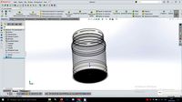
here is solidworks model of a mecanum wheel made by me.
grabcad
free

MECANUM WHEEL
...gle to the axis of rotation of the wheel. this makes the wheel exert force in diagonal direction when moving forward of backward.
grabcad
free

Mecanum Wheels Using Solidworks
...ngle to the axis of rotation of the wheel. this makes the wheel exert force in diagonal direction when moving forward of backward
Mecanum
thingiverse
free

Mecanum 50mm by RendiPambudi
...mecanum 50mm by rendipambudi
thingiverse
this is a mecanum wheel for omnidirectional mobile robot. hope you enjoy it
thingiverse
free

Arduino Mecanum Box
...ity.i share you and free
anyway ,this is box for mecanum carhttps://howtomechatronics.com/projects/arduino-mecanum-wheels-robot/
thingiverse
free

wheel mecanum by Joakim
...wheel mecanum by joakim
thingiverse
this is has many ancestors....http://www.thingiverse.com/search?q=mecanum&sa=search
thingiverse
free

Mecanum wheels robot by acicuecalo
...mecanum wheels robot by acicuecalo
thingiverse
omnidirectional mobile robot with mecanum wheels.
thingiverse
free

Mecanum Wheel with separate hub
...mecanum wheel with separate hub
thingiverse
mecanum wheel with separate hub, made for 5 mm shaft.
thingiverse
free

ftc mecanum wheel by cpodbob
...ftc mecanum wheel by cpodbob
thingiverse
i was wondering if i could make a set of ftc legal mecanum wheel
thingiverse
free

MECANUM WHEELS CAR
...mecanum wheels car
thingiverse
follow me on youtube!
thingiverse
free

Lego Mecanum Wheel by maxchambers3
...axchambers3
thingiverse
this is a custom made 3d printed mecanum wheel designed to work with lego power functions, nxt, and ev3.
thingiverse
free

FRC 2020 Mecanum Wheels
... infinite recharge,
mecanum wheels for ball intake.
https://twitter.com/istiklal7481
https://www.instagram.com/istiklalrobotics/
thingiverse
free

Nema 17 Mecanum
...nema 17 mecanum
thingiverse
making something like robomaster s1
Wheel
archibase_planet
free
Wheel
...l steering control steering wheel
wheel ship steering wheel n060215 - 3d model (*.gsm+*.3ds+*.max) for exterior 3d visualization.
3d_ocean
$14
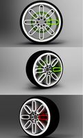
Wheel
...wheel
3docean
car rim car wheel rim wheel
high poly car wheel design. 16,840 polys
3d_export
free
wheel
...wheel
3dexport
wheel
3d_export
free
wheel
...wheel
3dexport
wheel
3d_export
free
Wheel
...wheel
3dexport
wheel
3d_export
$5

wheel
...wheel
3dexport
wheel for car.
3d_export
$5
wheel
...wheel
3dexport
car wheel
3d_export
$5
wheel
...wheel
3dexport
car wheel
3d_export
$5
wheel
...wheel
3dexport
car wheel
3d_export
$5
wheel
...wheel
3dexport
car wheel
Solidworks
turbosquid
$6

Practice in SolidWorks
... available on turbo squid, the world's leading provider of digital 3d models for visualization, films, television, and games.
turbosquid
$35

Pillar staircase solidworks
...ar staircase solidworks for download as stl, sldpr, and sldas on turbosquid: 3d models for games, architecture, videos. (1149346)
turbosquid
$40

Light bulb Solidworks
... available on turbo squid, the world's leading provider of digital 3d models for visualization, films, television, and games.
turbosquid
$13

Solidworks Parts Collection
...ollection for download as sldpr, sldas, sldpr, ige, and sldpr on turbosquid: 3d models for games, architecture, videos. (1638624)
turbosquid
$13

Metal workbench for garage. Solidworks
...el metal workbench for garage. solidworks for download as obj on turbosquid: 3d models for games, architecture, videos. (1478129)
turbosquid
$4

6 Nations Trophy SolidWorks
...ee 3d model 6 nations trophy solidworks for download as sldas on turbosquid: 3d models for games, architecture, videos. (1363060)
turbosquid
$20

METAL CHAIR SOLIDWORKS 2017
...del metal chair solidworks 2017 for download as stl and sldpr on turbosquid: 3d models for games, architecture, videos. (1226511)
turbosquid
$14

Metal Fence with spears solidworks
...etal fence with spears solidworks for download as ige and obj on turbosquid: 3d models for games, architecture, videos. (1478085)
turbosquid
$10

SolidWorks Standard wall bracket
...orks standard wall bracket for download as , sldpr, and sldas on turbosquid: 3d models for games, architecture, videos. (1241419)
3d_export
free
bank developed in solidworks 2020
...bank developed in solidworks 2020
3dexport