Thingiverse
![[MDN.RR] Remote-controlled Rover by JorgeMDN](/previews/10233966.jpg)
[MDN.RR] Remote-controlled Rover by JorgeMDN
by Thingiverse
Last crawled date: 2 years, 10 months ago
Inspired by Perseverance, the latest rover NASA sent to Mars, I designed this remote-controlled rover: MDN.RR. The MDN.RR is an all-wheel drive vehicle equipped with a 5 DOF arm, which can be used to pick up stuff or move a drone camera.
I used an ESP32 board (38-pin version) to decode the PWM signals from an 8-channel 2.4GHz receiver and control the vehicle accordingly. The coding was done in the Arduino IDE.
Each of the four legs consists of a shock absorber, a carbon fiber rod, a control arm (to keep the leg from bending outwards), a geared down DC motor (known as TT motor), an MG996R servo motor (which controls the direction of the wheel) and a 51105 thrust ball bearing (which holds the weight of the vehicle and allows the wheel to rotate with ease). The MDN.RR can be powered with a 2S lipo, which is strategically placed at a low location to optimize the stabilization of the vehicle by keeping the center of gravity as low as possible.
The CAD model can be viewed online at: https://a360.co/2T2VLZY. I highly recommend using the section analysis and exploded view functions to better understand how to assemble the rover.
List of 3D printed parts:
(2) Legs
(2) Legs (mirrored)
(2) Leg Holders
(2) Leg Holders (mirrored)
(4) Leg Spacers
(2) Control Arm Holders
(4) Shock Absorber Holders
(4) Motor Holders
(2) Wheels
(2) Wheels (mirrored)
(2) Frame - Part A
(2) Frame - Part B
(1) Electronics Holder
(4) LN298 Risers
(1) Battery Holder - Front
(1) Battery Holder - Rear
(1) Electronics Case - Front
(1) Electronics Case - Rear
(1) Arm Base
(1) Stepper Motor Gear
(1) Shoulder
(1) Shoulder Bearing Shaft
(1) Shoulder Bearing Holder
(1) Shoulder Cover
(1) Arm
(1) Forearm
(1) Wrist
(1) Gripper Gear
(2) Grippers
I included the STEP file of the wheel with no pattern, so you can design you own and test it on different surfaces.
List of electronics components:
(1) 2S (or even 3S) lipo battery
(1) ESP32 board (38-pin version)
(1) 2.4GHz transmitter (with at least 7 channels, one of which is a dial wheel)
(1) 2.4GHz receiver (7 channels)
(6) MG996R/MG995 servo motors (Metal gears)
(2) SG90 servo motors
(1) LN298 driver
(4) TT motors (Metal gears)
(1) 28-BYJ stepper motor and ULN2003 driver
(5) 30cm servo extension cables
(1) DC-DC LM2596 buck converter
(1) KCD1-101 rocker switch
List of hardware components:
(2) Zip ties
(2) 18x16x180mm (O.D.xI.D.xLength) carbon fiber rods
(4) 18x16x115mm (O.D.xI.D.xLength) carbon fiber rods
(4) 100mm shock absorbers
(4) 122mm connecting rods (I used the ones for the 1/10 RC Axial SCX10)
(5) 608RS ball bearings
(4) 51105 thrust ball bearings
(36) 6mm steel balls
(6) MG996R 25T circular horns
(1) M10x30 bolt, nut and washer
(1) Velcro strip (to hold the camera to the forearm)
I’ll update the hardware components list and assembly steps, and post a video within the next couple of days, but you can start printing the parts.
Similar models
grabcad
free

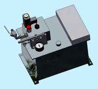
Vehicle wheel turning and shock absorber mechanism
...and shock absorber mechanism
grabcad
mini vehicle wheel turning and shock absorber mechanism with 8 tower pro mg995 servo motor.
grabcad
free

Shock Absorber
... absorbers keep your tires in contact with the road at all times.
this assembly consists
1.base rod
2. top rod
3. spring
4. nut
thingiverse
free

4 Wheel rover by Robin1985
...e arm holding the servos to make it fit the other side. two sets of wheels, if you prefer the curiosity or the opportunity wheel.
grabcad
free

Servo Motor MG996R
... robotic arm. the gears inside are metal and therefore we can achieve better precision and repeatability than with plastic gears.
thingiverse
free

Hobby Gear Motor Suspension by Ghost384904
...holds upper part of shock absorber
spring arm v2.2 screw holes recessed for wheel clearance
bushing added for upper part of shock
grabcad
free

Pipe Robot
...obot
grabcad
this assembly include:
1. dc motor with gearbox and encoder
2. ball screw and nut
3. bearing
4. gear
5. robot wheel
grabcad
free

Shock Absorb er Of Motor Byke Rear Wheel
...shock absorb er of motor byke rear wheel
grabcad
shock absorb er of motor byke rear wheel
3dwarehouse
free

Rover Plate
...rover plate
3dwarehouse
ballcaster holder stepper motor servo motor wheel ultrasonic sensor
thingiverse
free

Omni Wheel Robot by benyeung11994
... 2 controller
servo : emax es08aii x 8 pcs, mg 996r x 1
bearing : 4x7x2.5 mr74zz
38mm omniwheel x 4
130 dc plastic gear motor x 4
grabcad
free

servo motor tzy mg996r
...servo motor tzy mg996r
grabcad
servo motor model
tzy mg996r
Jorgemdn
thingiverse
free

MDN.RA - USB-Powered Robotic Arm by JorgeMDN
...bolt + (3) m3 nut
*(2) 6mm tact button switch
*(2) 10k ohm resistor
*(1) 3mm green led
*(1) 3mm red led
*(2) 220/330 ohm resistor
thingiverse
free
![[MDN.SP] 6DOF Stewart Platform by JorgeMDN](/t/8352486.jpg)
[MDN.SP] 6DOF Stewart Platform by JorgeMDN
...re using and click run.
if you are using the mpu6050, upload the
mdn.stewart_platform_arduinosketch_accel_v1 sketch to the board.
Mdn
3ddd
$1

modenese ART - MDNS SPL 011
...enese gastone , капитоне
итальянская коллекция спален leon doro фабрики modenese gastone
3dfindit
free

MDN
...mdn
3dfind.it
catalog: wmberg
3d_sky
free

modenese ART-MDNS SPL 011
...nese art-mdns spl 011
3dsky
gastone modenese italy kapitone
the italian collection of bedrooms leon doro factory modenese gastone
thingiverse
free

LED Matrix Bar Weather Station V1 by Zalophus
...and control as a wi-fi web server (wifimanager, ota, mdn) receives a message input from a user input page,...
thingiverse
free

Smart On Air Sign by AstralJaeger
...runs on a wemos d1 mini which hosts an mdn enabled web server with can be easily reached with...
thingiverse
free

Motor on a roller blind by pgote
...e.g. http://192.168.2.226 or http://{configured_name}.local if you are using an mdn supported device/client such as ios or osx you want...
thingiverse
free

ProfileBlock™ - Balancing Robot - DIY Robot Platform by Zalophus
...and station mode support ota (at local network) support mdn (at local network) touchosc udp control code: source code...
3dwarehouse
free

MDN
...mdn
3dwarehouse
college palois
3dwarehouse
free

PENDANT LAMP MDN-1139 - TRANSGLOBE
...pendant lamp mdn-1139 - transglobe
3dwarehouse
#pendant_light #pendant_lamp #pendant #lamp
3dwarehouse
free

old skool
...old skool 3dwarehouse mdn ...
Rr
3d_export
$8

rrs
...rrs
3dexport
rrús ricsson
3d_export
$15

rrs
...rrs
3dexport
rrús para telecomunicaciones
turbosquid
$25

ring RR
...turbosquid
royalty free 3d model ring rr for download as stl on turbosquid: 3d models for games, architecture, videos. (1215170)
turbosquid
$50

RR SVA
...oyalty free 3d model rr sva for download as 3dm, fbx, and obj on turbosquid: 3d models for games, architecture, videos. (1585646)
turbosquid
free

Jackson RR
... available on turbo squid, the world's leading provider of digital 3d models for visualization, films, television, and games.
design_connected
$20

InOut 82 RR
...ected
photo-realistic 3d models of the inout 82 rr lounge from gervasoni for 3d architectural and interior design presentations.
3d_export
$5

superbike s 1000 rr
...superbike s 1000 rr
3dexport
superbike s 1000 rr, motorcycle with perfect model.
3d_export
$10

rim RR 3D Model
...rim rr 3d model
3dexport
rim wheel
rim rr 3d model makc_damage 4525 3dexport
3ddd
free

CH030-8-RR Gramercy Home
...ch030-8-rr gramercy home
3ddd
gramercy home
люстра ch030-8-rr gramercy home
3d_export
$75

rr phantom ii
...n the crown, or india, to put it simply. the rr phantom ii star of india is currently valued at £ 8m. model created in cinema 4d.
Rover
3d_ocean
$89

Land-Rover Range Rover 2011
...andling have been transformed with the introduction of new engines, transmission and chassis systems. combine these enhancemen...
3d_export
$20

land rover
...land rover
3dexport
land rover
3d_export
$14

Land Rover Range Rover 2022
...land rover range rover 2022
3dexport
3d_export
$39

land rover range rover iii
... rover iii
3dexport
land rover range rover iii, year 2002.<br>model with high quality finishing on the outside and inside.
3d_export
$7

the rover
...the rover
3dexport
turbosquid
$5

Rover
...royalty free 3d model rover for download as max, obj, and fbx on turbosquid: 3d models for games, architecture, videos. (1673120)
3d_ocean
$89

Land Rover Range Rover 1986
...y, in real units of measurement, qualitatively and maximally close to the original. model formats: - *.max (3ds max 2008 scanl...
3d_export
$29

Land Rover Range Rover 1993 3D Model
... rover range rover 1993 3d model
3dexport
land rover range 1993
land rover range rover 1993 3d model 3dlogicline 39509 3dexport
3d_export
$69

Land Rover Range Rover Velar 2023
...land rover range rover velar 2023
3dexport
3d_export
$20

land rover range rover
...e apps.<br>car textures:png - 2k resolution other available formats: obj, 3ds, fbx, max. polycount: 35742 poly / 37163 tris
Remote
archibase_planet
free

Remote
...remote
archibase planet
tv remote remote controller remote
remote - 3d model for interior 3d visualization.
archibase_planet
free

Remote
...e
archibase planet
remote control remote controller remote
remote n140512 - 3d model (*.gsm+*.3ds) for interior 3d visualization.
turbosquid
$1

Remote
...
turbosquid
royalty free 3d model remote for download as obj on turbosquid: 3d models for games, architecture, videos. (1487515)
3d_export
$5
Tv Remote
...tv remote
3dexport
tv remote
3d_ocean
$7

Remote controller
... control switcher tv remote
remote controller for tv, sound systems etc easy to edit textures photo real rendered with mental ray
turbosquid
$39

remote
...free 3d model remote for download as obj, fbx, blend, and dae on turbosquid: 3d models for games, architecture, videos. (1387531)
turbosquid
$5

remote
...free 3d model remote for download as 3ds, obj, fbx, and blend on turbosquid: 3d models for games, architecture, videos. (1401849)
archive3d
free
Remote 3D Model
...l
archive3d
tv remote remote controller remote
remote - 3d model for interior 3d visualization.
turbosquid
$11
Remote
... available on turbo squid, the world's leading provider of digital 3d models for visualization, films, television, and games.
turbosquid
$10

remote
... available on turbo squid, the world's leading provider of digital 3d models for visualization, films, television, and games.
Controlled
3d_ocean
$4
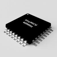
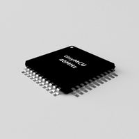
Controller TQFP32
...qfp32
3docean
chip controller cpu electronic gpu mcu micro controller silicon smd tqfp wafer
a micro controller in tqfp32 package
3d_ocean
$4
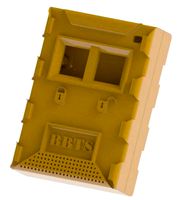
Controller TQFP44
...44
3docean
chip controller cpu electronic gpu mcu micro controller package smd tqfp tqfp44
a micro controller in a tqfp44 package
3d_export
$15
control unit
...control unit
3dexport
control unit
3ddd
$1
Yacht control
...yacht control
3ddd
yacht control
3d_export
$5
controle pgdm
...controle pgdm
3dexport
carcaca controle pgdm
turbosquid
free
controler
... available on turbo squid, the world's leading provider of digital 3d models for visualization, films, television, and games.
3ddd
$1

Control
...
http://www.schmitz-leuchten.de/html-ru/einzelleuchten-lampentyp-details.php?lamptype_no=700&group;=917&id;=731
3d_ocean
$4
Controller TQFP100
...100
3docean
chip computer cpu electronic gpu mcu micro controller pin platine silicon wafer
a micro controller in tqfp100 package
3d_ocean
$4
Controller TQFP64
...qfp64
3docean
chip computer cpu gpu mcu micro controller package silicon tqfp tqfp64 wafer
a micro controller in a tqfp64 package
3d_ocean
$7
Remote controller
... control switcher tv remote
remote controller for tv, sound systems etc easy to edit textures photo real rendered with mental ray