Thingiverse
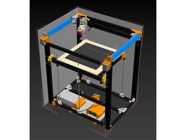
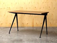
M-Bot, 400x300x400mm Build Volume, 3 leadscrews, Titan Aero direct drive, IR-bed leveling by MortarArt
by Thingiverse
Last crawled date: 3 years, 1 month ago
Most of the below is just for historical record. This is a deprecated design. See links below.
M-bot v.2; https://www.thingiverse.com/thing:3045974
M-bot v.3; https://www.thingiverse.com/thing:3134348
M-bot v.3.5; https://www.thingiverse.com/thing:3889891
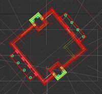
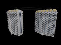
So far this is just a mockup, to determine extrusion lengths, and to accommodate the claimed features.
While there is two effectors on the X axis, I plan to start out with just one, and to figure out how the belts are run, in order to install a second.
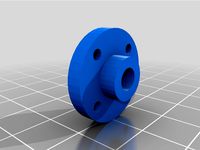
I'll be using KFL08 Shaft supports, for the three leadscrews, and I'll be installing them in different locations to the design by oeyhaga.
Much of my BOM is determined by the spare parts I have in stock already, and primarily it's the RobotDigg parts that I needed to purchase to get underway.
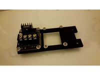
The hardware list is likely not accurate, since I'm removing quite a few parts from the original D-bot, such as the Z-end stop, which I'm replacing with an IR sensor, and the spool mount, as I have a rack above my existing printers that serves that purpose well.
/edit
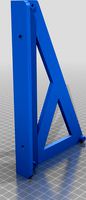
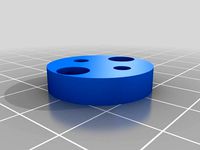
Some notes on the STL files uploaded so far: These are the parts required to install the 3 leadscrews. Any prospective assemblers will need to pay attention to how I have constructed my bottom frame, with the two wide 2020 extrusions, set back 20mm from the front and back of the bot.
The models were printed in solid ABS, using a 0.8mm volcano nozzle with 0.25mm layers. As a result they are much sturdier than equivalent PLA or PET-G prints might be. Good luck!
/edit2
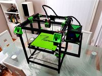
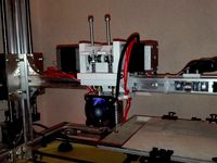
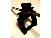
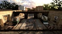
I've added two new photos to show my progress so far. The overview photo shows where I am at, approximately. I've wired together some of the electronics, but left everything with stock wire length because I'm not too sure how I'll arrange it all yet. The XY belts are attached, and pretty tight, though I'm not sure if they're tight enough. Endstops are in place.
/edit3
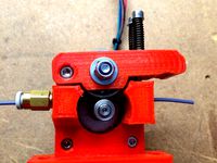
I am going to be starting out with this printer, using a bowden extruder of my own design. It's a simple, non-geared, clamp model, that I made using parts I had lying around, to drive the Volcano on my Kossel XL. It pushes filament quickly and reliably, and is cheap to make. You can find it here; https://www.thingiverse.com/thing:2423115
/edit4.1
I've got the Z axis moving cleanly, and accurately. Here is the parts list for this component:
For large (400x300mm XY build area) 1524mm GT2 belt
For regular D-bot 1200mm GT2 belt
3x anti-backlash nuts
3x Single start 8mm leadscrews
3x 40 tooth pulleys 8mm ID
3x pillow bearings 8mm ID
6x M5x8mm
6x t-nuts (pre-or-post install as needed)
Bearing tensioners (see note):
2x M5x40mm
4x t-nuts (pre-or-post install as needed)
6x M5 (OD <10mm) washer
2x M5 nuts
2x ID 5mm OD 14mm bearings
4x ID 5mm OD 16mm bearings
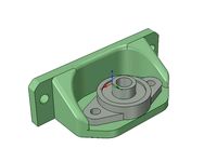
Z motor mount:
8x M3 washer
2x M3x10mm
2x M3x25mm
4x F623ZZ Flange Bearings
1x 20 tooth pulley 5mm ID
1x 0.9 step angle 48mm (1.68A) 5mm shaft Nema17* & **
2x M5x10mm
2x M5 washer
2x t-nuts (pre-or-post install as needed)
*Steps per MM 3200, maximum MM/min 400, mA 1680
**A note on the above. I'm now using a 60mm Nema17 for the Z axis, and while 400MM/min is possible, there was a few moments where the bed didn't want to move smoothly with the older motor, so I think slower speeds might be better.
Printed components:
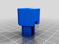
1x z-motor-mount-print
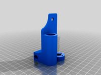
1x backlash-nut-mount-2040-rear
2x backlash-nut-mount-2040-print-x2
I don't have time to write instructions yet, but the most recent pictures I've put up show the final arrangement. The main complication, other than fitting, is to ensure that the leadscrews are installed parallel to the wheel guides. The way I did this (and it was sufficient), was to use a tape measure, to make sure that the top and bottom of the leadscrew were the same distance from the 2040 extrusions to within 0.5mm.
Note on bearing tensioners:
Assemble as following:
Place onto the bolt, towards the head; Large bearing, then washer, then small bearing, then washer, then large bearing, then washer, then M5 nut, fastened.
Then place a T nut around 10mm down the threads. And another T nut on the 2020 extrusion, and fix bolt to extrusion.
/edit5
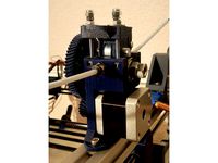
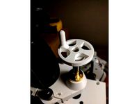
I got my beard stuck in the pulley over the X and Y motors while peering at prints so I designed and printed motor caps that are easy to print and install.
/edit6
I've added parts for the linear rod Titan Aero mount, which let me get acceleration up to 2400, with acceptable rigidity. I'll be adding more stiffness to the design for the rod ends. This is where I'm seeing the most vibration (only in short jerky infill moves) when I put acceleration above 4800. Feel free to ask about the parts required, but this is very much a beta setup.
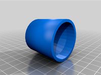
I've also uploaded an idler arm for the Titan, to allow the use of a grooved bearing I had on hand. Parts required; cap head M4x8mm bolt, bearing spacer / washer (I'm using an m5, but an m4 will work), OD10mm,ID5mm,4mm thick bearing (for motor shaft).
The idler arm is a remix of the design by Miklos Hejjas; https://grabcad.com/library/titan-aero-extruder-assembly-1
/edit7
This will be the last major update for this printer, as I am now building a second CoreXY printer, based on the lessons learned with this one. It will be listed separately as the M-BOT v2.
The main changes from edit6 are; I've deleted the linear rods, and returned to using a 2040 extrusion for the main moving components. The linear rods had far too much deflection for this scale of printer, and I should've known better ... should've done more research.
I've also updated each printed corner piece / carriage to have no part outside the extents of the extrusions, so that an enclosure can be easily fitted. This is a very enclosure friendly design.
Additionally, the printer could easily be constructed using these dimensions with a 400x300mm bed in mind, so I'll be updating the title to reflect that.
The effector I've selected is the AC-Bot Carriage, and I've had to make some modifications to it, to work with the components I had available. I'll also upload those.
I'll likely replace this text at some point with rough instructions, and put the updates in the files as a changelog.
M-bot v.2; https://www.thingiverse.com/thing:3045974
M-bot v.3; https://www.thingiverse.com/thing:3134348
M-bot v.3.5; https://www.thingiverse.com/thing:3889891
So far this is just a mockup, to determine extrusion lengths, and to accommodate the claimed features.
While there is two effectors on the X axis, I plan to start out with just one, and to figure out how the belts are run, in order to install a second.
I'll be using KFL08 Shaft supports, for the three leadscrews, and I'll be installing them in different locations to the design by oeyhaga.
Much of my BOM is determined by the spare parts I have in stock already, and primarily it's the RobotDigg parts that I needed to purchase to get underway.
The hardware list is likely not accurate, since I'm removing quite a few parts from the original D-bot, such as the Z-end stop, which I'm replacing with an IR sensor, and the spool mount, as I have a rack above my existing printers that serves that purpose well.
/edit
Some notes on the STL files uploaded so far: These are the parts required to install the 3 leadscrews. Any prospective assemblers will need to pay attention to how I have constructed my bottom frame, with the two wide 2020 extrusions, set back 20mm from the front and back of the bot.
The models were printed in solid ABS, using a 0.8mm volcano nozzle with 0.25mm layers. As a result they are much sturdier than equivalent PLA or PET-G prints might be. Good luck!
/edit2
I've added two new photos to show my progress so far. The overview photo shows where I am at, approximately. I've wired together some of the electronics, but left everything with stock wire length because I'm not too sure how I'll arrange it all yet. The XY belts are attached, and pretty tight, though I'm not sure if they're tight enough. Endstops are in place.
/edit3
I am going to be starting out with this printer, using a bowden extruder of my own design. It's a simple, non-geared, clamp model, that I made using parts I had lying around, to drive the Volcano on my Kossel XL. It pushes filament quickly and reliably, and is cheap to make. You can find it here; https://www.thingiverse.com/thing:2423115
/edit4.1
I've got the Z axis moving cleanly, and accurately. Here is the parts list for this component:
For large (400x300mm XY build area) 1524mm GT2 belt
For regular D-bot 1200mm GT2 belt
3x anti-backlash nuts
3x Single start 8mm leadscrews
3x 40 tooth pulleys 8mm ID
3x pillow bearings 8mm ID
6x M5x8mm
6x t-nuts (pre-or-post install as needed)
Bearing tensioners (see note):
2x M5x40mm
4x t-nuts (pre-or-post install as needed)
6x M5 (OD <10mm) washer
2x M5 nuts
2x ID 5mm OD 14mm bearings
4x ID 5mm OD 16mm bearings
Z motor mount:
8x M3 washer
2x M3x10mm
2x M3x25mm
4x F623ZZ Flange Bearings
1x 20 tooth pulley 5mm ID
1x 0.9 step angle 48mm (1.68A) 5mm shaft Nema17* & **
2x M5x10mm
2x M5 washer
2x t-nuts (pre-or-post install as needed)
*Steps per MM 3200, maximum MM/min 400, mA 1680
**A note on the above. I'm now using a 60mm Nema17 for the Z axis, and while 400MM/min is possible, there was a few moments where the bed didn't want to move smoothly with the older motor, so I think slower speeds might be better.
Printed components:
1x z-motor-mount-print
1x backlash-nut-mount-2040-rear
2x backlash-nut-mount-2040-print-x2
I don't have time to write instructions yet, but the most recent pictures I've put up show the final arrangement. The main complication, other than fitting, is to ensure that the leadscrews are installed parallel to the wheel guides. The way I did this (and it was sufficient), was to use a tape measure, to make sure that the top and bottom of the leadscrew were the same distance from the 2040 extrusions to within 0.5mm.
Note on bearing tensioners:
Assemble as following:
Place onto the bolt, towards the head; Large bearing, then washer, then small bearing, then washer, then large bearing, then washer, then M5 nut, fastened.
Then place a T nut around 10mm down the threads. And another T nut on the 2020 extrusion, and fix bolt to extrusion.
/edit5
I got my beard stuck in the pulley over the X and Y motors while peering at prints so I designed and printed motor caps that are easy to print and install.
/edit6
I've added parts for the linear rod Titan Aero mount, which let me get acceleration up to 2400, with acceptable rigidity. I'll be adding more stiffness to the design for the rod ends. This is where I'm seeing the most vibration (only in short jerky infill moves) when I put acceleration above 4800. Feel free to ask about the parts required, but this is very much a beta setup.
I've also uploaded an idler arm for the Titan, to allow the use of a grooved bearing I had on hand. Parts required; cap head M4x8mm bolt, bearing spacer / washer (I'm using an m5, but an m4 will work), OD10mm,ID5mm,4mm thick bearing (for motor shaft).
The idler arm is a remix of the design by Miklos Hejjas; https://grabcad.com/library/titan-aero-extruder-assembly-1
/edit7
This will be the last major update for this printer, as I am now building a second CoreXY printer, based on the lessons learned with this one. It will be listed separately as the M-BOT v2.
The main changes from edit6 are; I've deleted the linear rods, and returned to using a 2040 extrusion for the main moving components. The linear rods had far too much deflection for this scale of printer, and I should've known better ... should've done more research.
I've also updated each printed corner piece / carriage to have no part outside the extents of the extrusions, so that an enclosure can be easily fitted. This is a very enclosure friendly design.
Additionally, the printer could easily be constructed using these dimensions with a 400x300mm bed in mind, so I'll be updating the title to reflect that.
The effector I've selected is the AC-Bot Carriage, and I've had to make some modifications to it, to work with the components I had available. I'll also upload those.
I'll likely replace this text at some point with rough instructions, and put the updates in the files as a changelog.
Similar models
thingiverse
free

XY_Plotter by modelatolyesi
...
1x ball-pen spring.
electronics:
arduino uno
cnc shield.
2x a4988 stepper driver.
9g. servo.
4x micro switch.
extension cables.
thingiverse
free
Cyborg Geared Extruder for 3030 Extrusion by brainchecker
...3 nuts and washers
only part3 needs to be printed with supports.
printed in petg with an high amount of infill for good strength.
thingiverse
free
TornadoCube - Tevo Tornado CoreXY Conversion by cransjadel
...0mm or 1360mm closed gt2 belt
longer bowden tube for 1.75mm filament, 4mm od
other parts i used:
jst wire connectors
tl smoothers
thingiverse
free

Filament holder
...n testing stage.
required parts
8mm shaft
2x fl08 bearings
2x m5 bolts
4x m5 washers
2x m5 nuts
1x m3 bolt
1x m3 washer
1x m3 nut
thingiverse
free
PCB Drill Stand by modelatolyesi
...
2x id 9x90mm compression spring.
4x id 8 washers.
1w white led, mini on-off switch, 2xaaa battery holder, 10-15cm hook-up wire..
thingiverse
free
Mini Kossel 1.75mm extruder by wallie
...et head cap screw
2x spring
1x m5 pneumatic straight threaded-to-tube adapter, push in 4 mm 4mm male
tools
m5 manual screw tap
thingiverse
free
Anet AM6/AM8 Dual Mosfet Holder by _silaz
...m3 nut
2x m5x10
2x m5 washer
2x m5 hammer nut for aluminium extrusion
size of mosfet i use is 52mmx42mm from mid-hole to mid-hole
grabcad
free

Geared Tri Fidget Spinner
...rings.
printed parts:
1x top
1x bottom
3x small gears
1x big gear
2x caps
other parts required:
3x m8 hex nuts
1x 608zz bearing
thingiverse
free
POwer Supply / Suporte fonte 12v/24v AM8 by suelenbraga
...v/24v am8 by suelenbraga
thingiverse
power supply support for am8 (2040 extrusion).
3x m3x8
2x m5x8
2x t nut m5 to 2020 strusion
thingiverse
free
Dual Extruder by Psycho1981
...ng:
4x allen screw m5
4x square nut m5
4x washer m5
electronic:
-ramps 1.4 board
-atx power supply
-firmware "marlin"
Mortarart
thingiverse
free
Until we all belong. by MortarArt
...until we all belong. by mortarart
thingiverse
https://untilweallbelong.com/
thingiverse
free

Titan Aero IR mount by MortarArt
...ount by mortarart
thingiverse
a fitting for mounting an ir sensor to a titan aero.
the updated mount is for the duet3d ir mount.
thingiverse
free
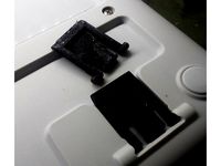
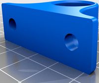
Leg for Logitech y-r0015 keyboard by MortarArt
...15 keyboard by mortarart
thingiverse
printed in petg. needed a little post-processing to get the nodules to fit in the recesses.
thingiverse
free
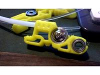
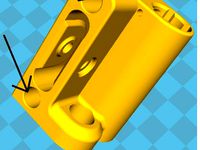
E3d Titan Idler Arm redesign by MortarArt
...edesign by mortarart
thingiverse
basically provides space for a bearing on the motor arm, and a grooved bearing against the hob.
thingiverse
free
Hex Adapter for screwdriver by MortarArt
...r
m3 nut
adapts a 1/4" hex on a screwdriver to 3, 4 & 5mm hex keys.
printed in solid abs, supportless. heated enclosure.
thingiverse
free
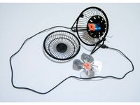
RS Components USB fan rebuild by MortarArt
...erse
a bracket to install a motor recovered from a cd/dvd drive to replace a broken motor in a usb powered fan by rs components.
thingiverse
free
Charlotte Valve with minimal manual support by MortarArt
...r more rapid production. thicker walls where the part joins the mask, and manual support for the remaining parts that require it.
thingiverse
free
Near-supportless Bladless Fan by MortarArt
...required, but only in internal areas. printing now ... hopefully it won't fail as it's a 24 hour print on a replicator 2.
thingiverse
free
Micro Lift by MortarArt
...ls, so that it can easily be moved along the formwork.
components could be a mix of aluminium or steel plates, and printed parts.
thingiverse
free
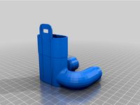
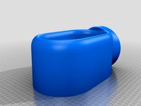
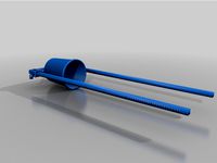
Greenhouse sprinkler (pour from outside) by MortarArt
...oviding a funnel on one end, and an outlet on the other, so that watering can be done without opening or entering the greenhouse.
Leadscrews
thingiverse
free
Leadscrew Support by The_Custom_Side
...w support for 8mm leadscrew.
printed in 0.25mm petg
requires bearing (16mm od, 8mm id).
no supports, no rafts, 20% gyroid infill.
thingiverse
free

Hook for M8 Leadscrew
...hook for m8 leadscrew
thingiverse
hook which holds on m8 leadscrew without pressure on the screw
thingiverse
free
X Idler Leadscrew by GOO2014
...x idler leadscrew by goo2014
thingiverse
x idler leadscrew
thingiverse
free
10mm Leadscrew Knob by carboncopy101
...10mm leadscrew knob by carboncopy101
thingiverse
this is a knob for a 10mm leadscrew for manual turning. enjoy.
thingiverse
free
nut for m5 leadscrew by mbzn
...nut for m5 leadscrew by mbzn
thingiverse
created to use as a nut for m5 threaded bar in place of a leadscrew
thingiverse
free
8mm Leadscrew Crank by dakahler
...igned for the cyclone pcb, but can be used on any 8mm leadscrew.
the captive nut for the set screw is designed to be heat-staked.
thingiverse
free
Z leadscrew support for KFL08 by bajmar
...z leadscrew support for kfl08 by bajmar
thingiverse
z leadscrew support for kfl08
thingiverse
free
X-Axis Leadscrew Idler by brisinger
...x-axis leadscrew idler by brisinger
thingiverse
x-axis leadscrew idler
thingiverse
free
Leadscrew Adapter by PhoenixZip
...rew, and it does not fit our lorei printers.
this adapter allows use of holes that are 16mm apart to our (roughly) 11.85mm holes.
thingiverse
free
Trintcore z-axis modified leadscrew by grubeludouche
... modified leadscrew by grubeludouche
thingiverse
this is a mod to fit a t8 pitch leadscrew, replacing the original m8 leadscrew.
Aero
3ddd
$1
AERO
...aero
3ddd
aero
стул, производитель aero. ссылка:http://www.mebelaero.ru/catalog/detail.html?id=6647
design_connected
$18
Aero
...aero
designconnected
wendelbo aero computer generated 3d model. designed by 365° north.
3ddd
$1
AERO BC30W
...aero bc30w
3ddd
aero , барный
артикул: bc30w
производитель: aero
3ddd
$1
TERMA AERO HG
...terma aero hg
3ddd
полотенцесушитель , aero
terma radiator aero hg
design_connected
$11
Aero Round
...aero round
designconnected
restoration hardware aero round computer generated 3d model.
design_connected
$11
Aero Oval
...aero oval
designconnected
restoration hardware aero oval computer generated 3d model.
design_connected
$16
Aero 027
...aero 027
designconnected
emu group aero 027 computer generated 3d model. designed by newman , paul.
3ddd
$1
desiree aero
...desiree aero
3ddd
фабрика - desiree
коллекция - aero
описание - диван/sofa
сайт -http://www.euromobil.com
design_connected
$11
Aero 026
...aero 026
designconnected
emu group aero 026 bar stools computer generated 3d model. designed by paul newman .
turbosquid
$12

aero plane
...
royalty free 3d model aero plane for download as max and fbx on turbosquid: 3d models for games, architecture, videos. (1544795)
Ir
turbosquid
$65
FLIR Vue Pro IR Camera
... available on turbo squid, the world's leading provider of digital 3d models for visualization, films, television, and games.
turbosquid
$10
Subwoofer F&D IHOO 5.1 IR
...oofer f&d ihoo 5.1 ir for download as sldpr, max, and ige on turbosquid: 3d models for games, architecture, videos. (1523229)
3ddd
$1

Grohe Eurosmart CE IR electronic
...t ce ir electronic
3ddd
grohe , смеситель
смеситель для раковины с инфракрасным сенсором
turbosquid
$40
AK 47 Dual Laser Sight with IR Illuminator
...k 47 dual laser sight with ir illuminator for download as obj on turbosquid: 3d models for games, architecture, videos. (1586129)
turbosquid
$30
IR Bracelet Light Therapy Pain Recovery System
...acelet light therapy pain recovery system for download as ige on turbosquid: 3d models for games, architecture, videos. (1493109)
3ddd
$1
GRAMERCY HOME - Bastian Chandelier CH058-5-IR
...5-ir
3ddd
gramercy home
gramercy home
bastian chandelier
ch058-5-ir
ширина 47 см
глубина 47 см
высота 25 см
www.gramercy-home.ru
turbosquid
$20
IR-RF PLC USB TRANSMITTER 2014 RAW
... available on turbo squid, the world's leading provider of digital 3d models for visualization, films, television, and games.
turbosquid
$2
Speakers Centr F-D - Sven IHOO 5-1 IR
... available on turbo squid, the world's leading provider of digital 3d models for visualization, films, television, and games.
turbosquid
$2
Speakers Front F-D F and D - Sven IHOO 5-1 IR
...) - sven ihoo 5-1 ir for download as max, ige, stl, and sldpr on turbosquid: 3d models for games, architecture, videos. (1144599)
3d_export
$15
be meyers mawl-c1 ir-laser
...station for more<br>tri count: 8,335 vertex count: 4,405 texture: pbr-4k<br>https://www.artstation.com/artwork/yaed4v
Bot
turbosquid
$19

Bot
... available on turbo squid, the world's leading provider of digital 3d models for visualization, films, television, and games.
turbosquid
$1

bot
... available on turbo squid, the world's leading provider of digital 3d models for visualization, films, television, and games.
turbosquid
free

Bot
... available on turbo squid, the world's leading provider of digital 3d models for visualization, films, television, and games.
3d_export
$10

scanner bot
...scanner bot
3dexport
cool scanner bot who scans for fixing things...
3d_ocean
$9

Apc Bot
...n bot games toys
an all-purpose-constructo-bot. for cartoon purposes. the model is not rigged. please use vray adv for rendering.
3d_export
$75
Bot 3D Model
...bot 3d model
3dexport
robot bot man kiborg character
bot 3d model evgen 19504 3dexport
turbosquid
free

Eye Bot
...eye bot
turbosquid
free 3d model eye bot for download as fbx on turbosquid: 3d models for games, architecture, videos. (1514059)
turbosquid
$29

Gorill-bot
...bosquid
royalty free 3d model gorill-bot for download as fbx on turbosquid: 3d models for games, architecture, videos. (1239456)
turbosquid
$25
Lamp Bot
...bosquid
royalty free 3d model lamp bot for download as blend on turbosquid: 3d models for games, architecture, videos. (1230121)
turbosquid
$10
Spectre Bot
...osquid
royalty free 3d model spectre bot for download as fbx on turbosquid: 3d models for games, architecture, videos. (1616378)
Titan
design_connected
$18

Titan
...titan
designconnected
original btc titan computer generated 3d model.
3d_ocean
$25
RMS Titanic
...rms titanic
3docean
ship steamer titanic
3d model of the rms titanic
turbosquid
$49
Titan
...quid
royalty free 3d model titan for download as obj and ztl on turbosquid: 3d models for games, architecture, videos. (1314276)
turbosquid
$8

Titan
...d
royalty free 3d model titan for download as , fbx, and obj on turbosquid: 3d models for games, architecture, videos. (1545505)
3d_export
$15

eren yeager titan from attack on titan
...eren yeager titan from attack on titan
3dexport
3d model of eren titan
3d_export
$5
titanic new
...titanic new
3dexport
titanic 3d model normal quality for animation
3d_export
$100
Titan 3D Model
...titan 3d model
3dexport
silo launcher rocket titan
titan 3d model acquarius 37854 3dexport
3d_ocean
$25
Titan
...nfs nfshs one ps ps1 psone rod speed sports stakes titan transport vehicle
quality exterior and low polygon interior concept car.
3ddd
$1

Titanic Lamp(table)
...titanic lamp(table)
3ddd
titanic lamp(table)
turbosquid
$10
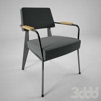
Titan chair
...osquid
royalty free 3d model titan chair for download as max on turbosquid: 3d models for games, architecture, videos. (1301533)
Volume
turbosquid
$20
Volume game
...royalty free 3d model volume game for download as obj and fbx on turbosquid: 3d models for games, architecture, videos. (1278990)
turbosquid
$29
Volume meter
... available on turbo squid, the world's leading provider of digital 3d models for visualization, films, television, and games.
turbosquid
free

volume light
... available on turbo squid, the world's leading provider of digital 3d models for visualization, films, television, and games.
turbosquid
$2
Volume Icon
...el 3d volume icon for download as max, 3ds, dxf, fbx, and obj on turbosquid: 3d models for games, architecture, videos. (1626508)
3ddd
$1
VOLUME TUB CHAIR
... 37" (94 cm)
depth: 37" (94 cm)
height: 28.5" (72 cm)
arm height: 20" (51 cm)
seat height: 16.5" (42 cm)
turbosquid
$4

Trust Volume Controller
...del trust volume controller for download as obj, c4d, and fbx on turbosquid: 3d models for games, architecture, videos. (1310035)
turbosquid
$10
creative volume con
... available on turbo squid, the world's leading provider of digital 3d models for visualization, films, television, and games.
3d_export
$5
basic close volume of bezel door
...rt
this is files for the basic close volume of the bezel door. the close volume of an automotive interior part in catia software
turbosquid
$15
Volume Sorting Conveyor
...onveyor for download as 3ds, dxf, obj, c4d, fbx, dae, and stl on turbosquid: 3d models for games, architecture, videos. (1460788)
3d_ocean
$7

Wood Planks - Volume 1
... the textures i’ve used over the last few years, soon i’ll post more volumes like this. each texture also comes with: *diffuse...
Direct
design_connected
free
Compas Direction
...compas direction
designconnected
free 3d model of compas direction by vitra designed by prouvé, jean.
design_connected
$18
Direction Pivotant
...direction pivotant
designconnected
vitra direction pivotant computer generated 3d model. designed by prouvé, jean.
turbosquid
$6
not direct the front
...oyalty free 3d model not direct the front for download as max on turbosquid: 3d models for games, architecture, videos. (1213034)
turbosquid
$10

Rails Direct
... available on turbo squid, the world's leading provider of digital 3d models for visualization, films, television, and games.
3d_export
$5

Picto toilet directions
...lude 3d files next to rhino6: x3dv, step, igus, obj and stl. double-sided, flipping changes the gender directions to the toilets.
3ddd
$1
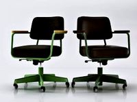
fauteuli direction
...d
chair , vitra , fauteuli
fauteuli vitra chair
design_connected
$18
Fauteuil Direction, 1951
...fauteuil direction, 1951
designconnected
vitra fauteuil direction, 1951 computer generated 3d model. designed by prouvé, jean.
3d_export
$5
Directional tactile 3D Model
...tactile 3d model
3dexport
directional tactile braille tile flooring interior
directional tactile 3d model renob000 71068 3dexport
turbosquid
$26

Radio direction finder A
...ty free 3d model radio direction finder a for download as fbx on turbosquid: 3d models for games, architecture, videos. (1212490)
turbosquid
$7

Wooden direction signage
...ty free 3d model wooden direction signage for download as max on turbosquid: 3d models for games, architecture, videos. (1453747)
Drive
turbosquid
$90
Drive
...turbosquid
royalty free 3d model drive for download as blend on turbosquid: 3d models for games, architecture, videos. (1654393)
3d_export
$10

cycloidal drive
...cycloidal drive
3dexport
cycloidal drive
3d_ocean
$5
Flash Drive
...h drive included : – materials – scene ( lighs / room ) – .c4d + .obj for any questions please feel free to contact me thank you.
3d_ocean
$5

Usb drive
...s shaders and a lighting setup. it also has a small animation of it going in and out. i saved it out as both a .blend file and...
3d_ocean
$5

Pen Drive
...est computer drive game model good low poly new pen pen drive textured unwrapped uv very low poly
a very beautiful low poly model
3d_ocean
$10
External hard drive
... is a detailed model of a trekstor external hard drive. you can easily modify the label on the top. simply edit the text objects.
turbosquid
$60

Star Drive
...squid
royalty free 3d model star drive for download as blend on turbosquid: 3d models for games, architecture, videos. (1254314)
turbosquid
$50
Star Drive
...squid
royalty free 3d model star drive for download as blend on turbosquid: 3d models for games, architecture, videos. (1263524)
turbosquid
$45
Star Drive
...squid
royalty free 3d model star drive for download as blend on turbosquid: 3d models for games, architecture, videos. (1287060)
turbosquid
$40
Star Drive
...squid
royalty free 3d model star drive for download as blend on turbosquid: 3d models for games, architecture, videos. (1261902)
Leveling
design_connected
$11

Levels
...levels
designconnected
one nordic levels computer generated 3d model. designed by form us with love.
design_connected
$7
Level
...level
designconnected
zanotta level shelves and storage computer generated 3d model. designed by arik levy.
turbosquid
$29
level
...ty free 3d model level for download as 3ds, obj, c4d, and fbx on turbosquid: 3d models for games, architecture, videos. (1272856)
turbosquid
$1
level
... available on turbo squid, the world's leading provider of digital 3d models for visualization, films, television, and games.
3d_export
$5

Mario level
...mario level
3dexport
mario level low quality for fun videos
3ddd
$1
LEVELS OF DISCOVERY
...етская мебель "levels of discovery". rab10003 princess mini rocker
кресло-качалка (мини) "принцесса навсегда"
3d_export
$19
level design
...level design
3dexport
you can use this design (level design) in your own game.
turbosquid
$60
Desert level
...squid
royalty free 3d model desert level for download as fbx on turbosquid: 3d models for games, architecture, videos. (1208131)
turbosquid
$15
Transit Level
...quid
royalty free 3d model transit level for download as max on turbosquid: 3d models for games, architecture, videos. (1158112)
turbosquid
$14

Districts Level
...id
royalty free 3d model districts level for download as max on turbosquid: 3d models for games, architecture, videos. (1408410)
Bed
3ddd
$1
bed
...bed
3ddd
bed , постельное белье
bed
3ddd
$1
bed
...bed
3ddd
bed , постельное белье
bed
3ddd
$1
bed
...bed
3ddd
bed , постельное белье
bed
3ddd
$1
bed
...bed
3ddd
bed , постельное белье
bed
3ddd
$1
bed
...bed
3ddd
bed , постельное белье
bed
3ddd
$1

bed
...bed
3ddd
bed , постельное белье
bed
3ddd
free
bed
...bed
3ddd
bed , постельное белье
bed
3ddd
free
bed
...bed
3ddd
bed , постельное белье
bed
3ddd
$1
Bed
...bed
3ddd
bed , постельное белье , постель
bed
3d_export
$7
bed adairs bed
...rs bed
3dexport
bed adairs bed in modern style. if you want a smoother surface, please turn on turbosmooth in the modifier list.
M
turbosquid
$20
Stage M&M
... available on turbo squid, the world's leading provider of digital 3d models for visualization, films, television, and games.
3ddd
$1

bag m&m's
...bag m&m's
3ddd
bag m&m's
bag m&m;'s
3d_export
$35
iskander m
...iskander m
3dexport
iskander m 3d model
design_connected
$7
barstool m
...barstool m
designconnected
barstool m computer generated 3d model.
3ddd
free
CACTUS M
...cactus m
3ddd
cactus , lzf
настольный светильник cactus m
производитель lzf
design_connected
$13
Anfora M
...anfora m
designconnected
lzf anfora m computer generated 3d model. designed by herranz, miguel.
3ddd
$1
зеркало M Gastone
...зеркало m gastone
3ddd
зеркало m gastone
зеркало m gastone
design_connected
$16
Dogon M
...dogon m
designconnected
emmemobili dogon m chairs computer generated 3d model. designed by ferruccio laviani.
design_connected
$9
Sunlight M
...sunlight m
designconnected
bonacina pierantonio sunlight m computer generated 3d model. designed by bizzozzero, franco.
3ddd
$1
Karman / Norma-M
...arman , norma-m
http://www.karmanitalia.it/en/prodotto/norma-m/norma-m-ap640n/
3
turbosquid
$10
Mountain Bike 3 -3 of 3
...model mountain bike 3 (#3 of 3) for download as fbx and blend on turbosquid: 3d models for games, architecture, videos. (1438752)
turbosquid
$6

Rock 3-3
...urbosquid
royalty free 3d model rock 3-3 for download as obj on turbosquid: 3d models for games, architecture, videos. (1628065)
turbosquid
$29
Books 150 pieces 3-3-3
...books 150 pieces 3-3-3 for download as max, obj, fbx, and stl on turbosquid: 3d models for games, architecture, videos. (1384033)
turbosquid
$3

Genesis 3 Clothing 3
... available on turbo squid, the world's leading provider of digital 3d models for visualization, films, television, and games.
3d_export
$5
hinge 3
...hinge 3
3dexport
hinge 3
3ddd
$1
Розетка 3
...розетка 3
3ddd
розетка
розетка 3
turbosquid
$50

is-3
... available on turbo squid, the world's leading provider of digital 3d models for visualization, films, television, and games.
turbosquid
$10
Mountain Bike 3 -2 of 3
...model mountain bike 3 (#2 of 3) for download as fbx and blend on turbosquid: 3d models for games, architecture, videos. (1438750)
turbosquid
$10
Mountain Bike 1 -3 of 3
...model mountain bike 1 (#3 of 3) for download as fbx and blend on turbosquid: 3d models for games, architecture, videos. (1438743)
3d_export
$5

3 CATS
...3 cats
3dexport
3 cats pen holder
Build
archibase_planet
free
Building
...building high-rise building office building construction
building n050115 - 3d model (*.gsm+*.3ds) for exterior 3d visualization.
3d_export
$5
building
...building
3dexport
clasic building
3ddd
$1
building
...building
3ddd
здание
building
archibase_planet
free
Building
...lanet
building office office building construction
building n090914 - 3d model (*.gsm+*.3ds+*.max) for exterior 3d visualization.
archibase_planet
free
Building
...net
building tower construction high-rise building
building n100214 - 3d model (*.gsm+*.3ds+*.max) for exterior 3d visualization.
3d_export
free
Building
...building
3dexport
low poly building;
3d_export
free
Building
...building
3dexport
low poly building;
3d_export
free
Building
...building
3dexport
low poly building;
3d_export
free
Building
...building
3dexport
low poly building;
3d_export
free
Building
...building
3dexport
low poly building;