Thingiverse

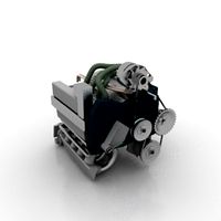
Low Bypass Turbofan Jet Engine by gahwar
by Thingiverse
Last crawled date: 3 years ago
xxxxxx
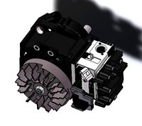
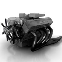
Revision 1 (file Rev_1.zip) see second picture
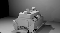
added combustion liner (Single Annular Can), fuel nozzles and turbine stand (in three pieces)
xxxxxx
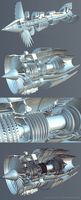
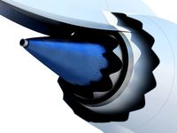
This is a first step study around a working 50 Kg thrust engine, a simplified model aimed to study the assembly sequences, volumes and components' layout in general. Once completed it will sit on my desk as a display model and the second design phase will include the theoretical studies outputs.
In order to decrease the complexity of the model you'll notice some conceptual mistakes (such as the bearings directly mounted on hot components like the HP and LP nozzles, compressor disks shapes and approximate aerodynamic profiles) but besides that, the model is created reflecting the actual design of the full size/working engines.
The combustion chamber and fuel injectors are missing, they will be included in the rev. 1.
If you'd like to build this thing you need the following items. I got them from e-bay and/or hobbyking.com
Bearings:
LP rotor: #2 688zz
HP rotor #1 6705zz, #1 6810zz
Hardware:
LP shaft: threaded rod M8 L=220
6 Metal push rod M3x300 (from hobbyking)
M2x6
M2x8
M2x10
M2.5x10
epoxy glue
LP Fan:
12 Blade High-Performance 120mm EDF Ducted Fan Unit (from hobbyking)
Tools:
sand paper
files
drill bits (1.5 , 2 , 2.5 and 3mm) or reamers
hobby woodcraft lathe (optional)
I printed all the big items at medium resolution (0.25), 10% infill and wall thickness set to 2 shells. Complex and small items like statoric vanes an compressor disks were printed at high res. (0.15)
For the compressor rotor assembly you need to cut the M3 Push Rods to the right length and weld (I used an electric welding solder) an M3 nut at the not threaded end.
For the external shell I used the ducted fan shroud (see picture). The gap between the modified fan shroud and the right turbine length has been filled with the printed component "ÃÂÃÂÃÂÃÂÃÂÃÂÃÂÃÂÃÂÃÂÃÂÃÂÃÂÃÂÃÂÃÂÃÂÃÂÃÂÃÂÃÂÃÂÃÂÃÂÃÂÃÂÃÂÃÂÃÂÃÂÃÂÃÂExternal can.stl".ÃÂÃÂÃÂÃÂÃÂÃÂÃÂÃÂÃÂÃÂÃÂÃÂÃÂÃÂÃÂÃÂÃÂÃÂÃÂÃÂÃÂÃÂÃÂÃÂÃÂÃÂÃÂÃÂÃÂÃÂÃÂÃÂ
Printed parts have been painted with glossy black as base coat and finished with lacquer metalizer.
All the printed parts require sanding, filing and reaming in order to correctly mate and allow the rotors to spin with no interference. A small lathe would help.
Pictures of the completed model, along with assembly instructions will follow.
Revision 1 (file Rev_1.zip) see second picture
added combustion liner (Single Annular Can), fuel nozzles and turbine stand (in three pieces)
xxxxxx
This is a first step study around a working 50 Kg thrust engine, a simplified model aimed to study the assembly sequences, volumes and components' layout in general. Once completed it will sit on my desk as a display model and the second design phase will include the theoretical studies outputs.
In order to decrease the complexity of the model you'll notice some conceptual mistakes (such as the bearings directly mounted on hot components like the HP and LP nozzles, compressor disks shapes and approximate aerodynamic profiles) but besides that, the model is created reflecting the actual design of the full size/working engines.
The combustion chamber and fuel injectors are missing, they will be included in the rev. 1.
If you'd like to build this thing you need the following items. I got them from e-bay and/or hobbyking.com
Bearings:
LP rotor: #2 688zz
HP rotor #1 6705zz, #1 6810zz
Hardware:
LP shaft: threaded rod M8 L=220
6 Metal push rod M3x300 (from hobbyking)
M2x6
M2x8
M2x10
M2.5x10
epoxy glue
LP Fan:
12 Blade High-Performance 120mm EDF Ducted Fan Unit (from hobbyking)
Tools:
sand paper
files
drill bits (1.5 , 2 , 2.5 and 3mm) or reamers
hobby woodcraft lathe (optional)
I printed all the big items at medium resolution (0.25), 10% infill and wall thickness set to 2 shells. Complex and small items like statoric vanes an compressor disks were printed at high res. (0.15)
For the compressor rotor assembly you need to cut the M3 Push Rods to the right length and weld (I used an electric welding solder) an M3 nut at the not threaded end.
For the external shell I used the ducted fan shroud (see picture). The gap between the modified fan shroud and the right turbine length has been filled with the printed component "ÃÂÃÂÃÂÃÂÃÂÃÂÃÂÃÂÃÂÃÂÃÂÃÂÃÂÃÂÃÂÃÂÃÂÃÂÃÂÃÂÃÂÃÂÃÂÃÂÃÂÃÂÃÂÃÂÃÂÃÂÃÂÃÂExternal can.stl".ÃÂÃÂÃÂÃÂÃÂÃÂÃÂÃÂÃÂÃÂÃÂÃÂÃÂÃÂÃÂÃÂÃÂÃÂÃÂÃÂÃÂÃÂÃÂÃÂÃÂÃÂÃÂÃÂÃÂÃÂÃÂÃÂ
Printed parts have been painted with glossy black as base coat and finished with lacquer metalizer.
All the printed parts require sanding, filing and reaming in order to correctly mate and allow the rotors to spin with no interference. A small lathe would help.
Pictures of the completed model, along with assembly instructions will follow.
Similar models
thingiverse
free

115mm spool fork by sici
...0lãâ©ãâãâ·x9~12ãâ¥ãâãâ
ãâ¦ãâ©ãâ¡ãâ§ãâãâ®ãâ§ãâãâ2ãâ¦ãâ¢ãâhttps://www.facebook.com/groups/562208953848064/
grabcad
free

Turbo Rotor, turbine - compressor, wheel - blisk - fan, impeller, Turbocharger
...eel - blisk - fan, impeller, turbocharger
grabcad
turbo rotor, turbine - compressor, wheel - blisk - fan, impeller, turbocharger
thingiverse
free

Filament guide replacement for Eventorbot direct extruder by Sungod3k
...re. this one a problem in the first version (http://www.thingiverse.com/thing:172076) and should be substantially reduced by now.
blendswap
free

pearHI
... ãâ¬ãâµãâ°ãâ»ãâ¸ãâãâãâ¸ãâ¡ãâ½ãâ¾ãâ¹.latest change on 2013/04/19, 08:58:52ðºð¾ññðµðºñð¸ñð¾ð²ðºð° ñðµðºññð°
thingiverse
free

Shrek (The Ogrelord) ( áð ÃÂàáð) ( áð ÃÂàáð) ( áð ÃÂàáð) ( áð ÃÂàáð) by Badfish2
...â ãâ¡ãâ°) ( ãâ¡ãâ° ãâãâ ãâ¡ãâ°) by badfish2
thingiverse
shrek is love. shrek is life. ( ãâ¡ãâ° ãâãâ ãâ¡ãâ°)
blendswap
free

2014 newyear forest
...¹ãâ¹ ãâ¸ãâ½ãâãâãâ¬ãæãâ¼ãâµãâ½ãâ, ãâ²ãâãâµãâ¼ ãâºãâãâ¾ ãâµãâ³ãâ¾ ãâãâ¾ãâ·ãâ´ãâ°ãâ²ãâ°ãâ».
thingiverse
free

Blade-1ã¯ã¼ãªã³ã°ãÂÂã¡ã³ãÂÂãºã« by Hotproceed
...â°ã£ââã£ââ¡ã£ââ³ã£ââã£ââã£ââã£ââ«ã¥â
â¥ã£ââ£ã£ââ¦ã£ââã£ââã£ââã£ââºã£ââ«ã£ââã£ââ¼ã£ââ¿ã£ââ§ã£ââã£ââ
grabcad
free

Core engine assembly for CFM56
...nd rotor blades which represent the high pressure compressor (hpc),combustion chamber assembly,1 stage of high pressure turbine.
thingiverse
free

N-DO badge by hare081987
...n-do badge by hare081987
thingiverse
ã â¸âã â¸â£ã â¸â²ã â¸âã â¸â±ã â¹âã â¸â¡ã â¹âã â¸âã â¹âã â¸âã â¸âã â¸â¹
thingiverse
free

Integrated Spool Holding System for the Felix Robotics Printer by Pacificimc
...ãâãâ¢ãâãâãâãâãâãâãâãâsolid and very little filament resistanceãâãâãâãâ¢ãâãâãâãâãâãâãâãâ
Gahwar
thingiverse
free

motorcycle piston by gahwar
...motorcycle piston by gahwar
thingiverse
this is a simplified model of a piston from an honda cbr900rr my 2003
thingiverse
free

Formula 1 rear tire by gahwar
...formula 1 rear tire by gahwar
thingiverse
rear tire for my bbs rim
thingiverse
free

Formula 1 Rear Rim by gahwar
...formula 1 rear rim by gahwar
thingiverse
this is a bbs rear rim form a my 1999 formula 1 car
thingiverse
free

Stage 1 bucket from an heavy duty gas turbine by gahwar
...stage 1 bucket from an heavy duty gas turbine by gahwar
thingiverse
from a 10mw heavy duty gas turbine
thingiverse
free

Oval Pistons Engine by gahwar
...em as per your needs.
other parts of the engine will follow.
you may want to take a look at my other things as well.
enjoy!
thingiverse
free

V2 Sports Motorbike Engine by gahwar
... easy at all .there are well defined processes to be followed, and few grindings required for some of the printed parts.
enjoy.
thingiverse
free

WWII stealth plane, Horten 229, aircraft model kit by gahwar
...del (570mm wingspan).
rev.1
added a zip file with all the parts.
what else... enjoy!
printing is ongoing, more pics will come
Turbofan
3d_ocean
$55
Turbofan Engine
...turbofan engine
3docean
3d engine model plane rocket rotation turbofan
turbofan engine modeler from real blueprints.
turbosquid
$20

Turbofan Engine
... available on turbo squid, the world's leading provider of digital 3d models for visualization, films, television, and games.
turbosquid
$7

Turbofan
...alty free 3d model engine nacelle for download as c4d and obj on turbosquid: 3d models for games, architecture, videos. (1568091)
turbosquid
$120

TURBOFAN COFFEE TABLE 2019
... free 3d model turbofan coffee table 2019 for download as max on turbosquid: 3d models for games, architecture, videos. (1435613)
turbosquid
$499

D-18T turbofan cutaway
... available on turbo squid, the world's leading provider of digital 3d models for visualization, films, television, and games.
turbosquid
$90

TURBOFAN COFFEE TABLE 2019 RAW
...e 3d model turbofan coffee table 2019 raw for download as max on turbosquid: 3d models for games, architecture, videos. (1435602)
3d_export
$8
General Electric GEnx turbofan jet engine 3D Model
...engine 3d model
3dexport
jet engine boeing aircraft turbo
general electric genx turbofan jet engine 3d model tasal 60160 3dexport
turbosquid
free

Turbofan Jet Engine ( T J E ).max
... available on turbo squid, the world's leading provider of digital 3d models for visualization, films, television, and games.
3d_export
$229

pw gtf geared turbofan engine - cutaway
...y problem in this model, please do not hesitate to contact us, we are looking forward to continuously dealing with you. markos 3d
3d_export
$229

f100 - pw - 220 turbofan engine - cutaway
...y problem in this model, please do not hesitate to contact us, we are looking forward to continuously dealing with you. markos 3d
Bypass
turbosquid
$20

Opal Bypass Earrings
... available on turbo squid, the world's leading provider of digital 3d models for visualization, films, television, and games.
turbosquid
$20

Opal Bypass Ring
... available on turbo squid, the world's leading provider of digital 3d models for visualization, films, television, and games.
turbosquid
$19

Pear bypass ring
... bypass ring for download as 3dm, 3dm, dwg, fbx, obj, and stl on turbosquid: 3d models for games, architecture, videos. (1579591)
3d_export
$19

Large Bypass Lopper 3D Model
...ors pruning twigs branches plastic handle carbon steel tool instrument hand
large bypass lopper 3d model humster3d 96493 3dexport
turbosquid
$3

Bypass Damper With VMA and Thermostat
... available on turbo squid, the world's leading provider of digital 3d models for visualization, films, television, and games.
turbosquid
$19

Bypass Bracelet with Pearls and Diamonds
...and diamonds for download as 3dm, lwo, 3ds, fbx, obj, and stl on turbosquid: 3d models for games, architecture, videos. (1566111)
turbosquid
$14

Bypass Ring with Pearls and Diamonds
...and diamonds for download as 3dm, lwo, 3ds, fbx, obj, and stl on turbosquid: 3d models for games, architecture, videos. (1565698)
3d_export
$5

Air bypass valve 3D Model
... bypass valve 3d model
3dexport
valve; pipe; tube; duct; flap;vent; piston; valvula
air bypass valve 3d model swan 59072 3dexport
humster3d
$15

3D model of Large Bypass Lopper
...detailed 3d model of large bypass lopper in various file formats. all our 3d models were created maximally close to the original.
turbosquid
$19

Bypass Ring with 3 big gems
...h 3 big gems for download as 3dm, 3dm, dwg, fbx, obj, and stl on turbosquid: 3d models for games, architecture, videos. (1576975)
Jet
turbosquid
$1

jet
...jet
turbosquid
royalty free 3d model jet for download as fbx on turbosquid: 3d models for games, architecture, videos. (1659892)
3ddd
free

water jet
...water jet
3ddd
фонтан
water jet fountain
turbosquid
$65

JETS
... available on turbo squid, the world's leading provider of digital 3d models for visualization, films, television, and games.
turbosquid
$10

jet
... available on turbo squid, the world's leading provider of digital 3d models for visualization, films, television, and games.
turbosquid
$10

Jet
... available on turbo squid, the world's leading provider of digital 3d models for visualization, films, television, and games.
turbosquid
$10

jet
... available on turbo squid, the world's leading provider of digital 3d models for visualization, films, television, and games.
turbosquid
$4

jet
... available on turbo squid, the world's leading provider of digital 3d models for visualization, films, television, and games.
turbosquid
$1

Jet
... available on turbo squid, the world's leading provider of digital 3d models for visualization, films, television, and games.
turbosquid
free

Jet
... available on turbo squid, the world's leading provider of digital 3d models for visualization, films, television, and games.
turbosquid
free

jet
... available on turbo squid, the world's leading provider of digital 3d models for visualization, films, television, and games.
Engine
3d_export
$5
engine
...engine
3dexport
engine
3d_export
free
Engine
...engine
3dexport
engine
archibase_planet
free
Engine
...engine
archibase planet
motor engine
engine - 3d model for interior 3d visualization.
archibase_planet
free
Engine
...engine
archibase planet
motor engine mover
engine n170708 - 3d model (*.3ds) for interior 3d visualization.
archibase_planet
free

Engine
...engine
archibase planet
engine locomotive train
locomotive - 3d model for interior 3d visualization.
turbosquid
$1

ENGINE
...osquid
royalty free 3d model ic engine for download as sldas on turbosquid: 3d models for games, architecture, videos. (1382781)
3d_export
$5

engine
...engine
3dexport
3d_export
free
engine
...engine
3dexport
turbosquid
$7

Engine
...d model animated engine mograph element3d for download as c4d on turbosquid: 3d models for games, architecture, videos. (1380716)
turbosquid
$1
ENGINE
...y free 3d model engine for download as max, 3ds, stl, and fbx on turbosquid: 3d models for games, architecture, videos. (1673703)