Thingiverse
Linear Piston for a Magnetic Repulsion Electric Generator.
by Thingiverse
Last crawled date: 4 years, 3 months ago
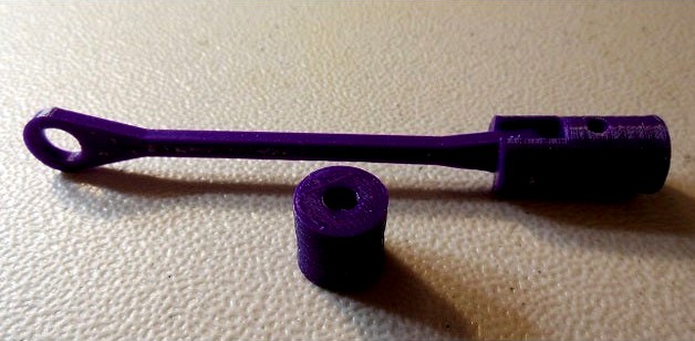
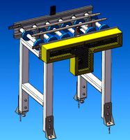
This is a linear piston that will be used in a Magnetic Electric Generator project. This is currently a work in progress. The goal is to create a Magnetic Repulsion Piston that uses 1/2 inch N50 grade Neodymium Cylindrical Magnets. The piston will move linearly through a set of coils to generate Voltage and Current.
One preliminary test produced 7.2V DC with an output current of 1.0 Amps at 1300 RPM passing the piston through 3 Magnet Wire Coils that were 1/4 inch wide with 25 Feet of Magnet Wire wrapped around each Coil. The output measurements were taken across all of the coils which were connected in parallel. The Linear Piston does not have to move far about 1.25 inches back and forth through the 3 Magnet Wire Coils.
For each revolution of the drive wheel the repulsion piston will induce 6 power pulses inside of each individual coil. Since the magnets are 1/2 inch long the the North Pole is
approximately 1/4 inch long and the South Pole is approximately 1/4 inch long. So, a good starting point is to make sure the air gap between the two magnetic poles that are facing each other in a repulsion configuration are spaced 1/4 inches apart. This air gap distance produces good results. If you think of the magnetic field lines as a traveling wavefront you can try different coil wrapping techniques to study how they respond when a magnetic field is moving through them. A piece of magnetic film is useful to see the magnetic field lines in the repulsion area of the linear piston.
KS Metals sales brass tubing in 12 inch lengths which can be found at ACE Hardware stores. I got a 1/2 inch diameter tube to hold the 1/2 Neodymium Magnets. I got a 17/32 inch diameter brass tube to wrap the magnet wire coils around. The 1/2 brass tube will slide back and forth inside the 17/32 brass tube. The distance between the surface of magnets to the start of the magnet wire in the coils is around 45.25 thousandths of an inch. A light machine oil should be applied between the brass tubes to reduce friction. The closer you can get the magnet wire coils to the surface of the magnets the stronger the magnetic field is which will produce more Voltage and Current at a specific RPM.
I am trying to use 3D printing to build a small desktop version and get close to these same results.
These parts were designed using the Freeware Version of the EMachineShop software.
To watch a Video about this Linear Piston Generator project visit the following YouTube
link:
https://youtu.be/vvqzisL-Zrg
Similar models
thingiverse
free

Scotch Yoke linear driven Magnetic Repulsion Piston.
...al drive shaft and scotch yoke pin.
these 3d parts were designed using the freeware version of the emachineshop software package.
thingiverse
free

variable magnetic field humbucker by rdubouil
...till a little bit present which gives a unique configuration.
adding the option to split the pickup gives even more possibilities
grabcad
free

Coil
...asically when the neodymium magnet moves, it generate electricity and light up the leds.
led
neodymium
circuit board
copper wire
grabcad
free

DC Motor
... parts of the dc motor. a tutorial to it from the youtube channel, solidworks tutorials is also added if you want to recreate it.
grabcad
free

Solenoid
...ound a metallic core, which produces a uniform magnetic field in a volume of space when an electric current is passed through it.
grabcad
free

Low RPM Magnet Generator 1 - 2 kW
... pcs (3 phase).
number of turns in coil = 145.
wire diameter: 1.12 mm
60 volts = about 250 rpm
use: water power, wind power, etc.
thingiverse
free

Linear Motion Machine using Rack & Pinion and Lever & Fulcrum Techniques.
... device while it is being operated.
these 3d parts were designed using the freeware version of the emachineshop software package.
thingiverse
free

Linear Magnetic Piston Center Punch Crimping Tool for 1/2 diameter Brass Tubes
... punches to the crimping tool handles.
these parts were designed using the freeware version of the emachineshop software package.
thingiverse
free

Coil Housing by OregonStateRheology
...oregonstaterheology
thingiverse
this is a coil housing. with wires wrapped around it, an electromagnetic field can be generated.
3dwarehouse
free

Brushless internal propulsion motor
...near velocity, l is distance between conductors of exciting coil. #electric_motor #internal_propulsion #internal_propulsion_motor
Repulsion
turbosquid
$7

dark repulser
...quid
royalty free 3d model dark repulser for download as obj on turbosquid: 3d models for games, architecture, videos. (1331380)
turbosquid
$7

Sword - Dark Repulser
... available on turbo squid, the world's leading provider of digital 3d models for visualization, films, television, and games.
3d_export
$6

Dark repulser sword
...051392 vertices - 2527166 unusual sword is made in 2 colors, everything is smoothed. if you have any questions or wishes - write.
turbosquid
$3

Dark Repulser Kirito Sword SAO Lowpoly Style
... kirito sword sao lowpoly style for download as blend and fbx on turbosquid: 3d models for games, architecture, videos. (1691216)
turbosquid
$26

Sao Kirtos Dark Repulser Sword cosplay prop
...word cosplay prop for download as max, dwg, fbx, obj, and stl on turbosquid: 3d models for games, architecture, videos. (1587623)
3d_export
free

elucidator
...ord art online. this sword is a demonic monster drop from a boss on the 50th floor that kirito wields along with «dark repulser».
3d_export
$10

railgun
...also acts on the rails, leading them to mutual repulsion<br>mostly the model is used in unity. for animation, write...
3d_export
$30

hms prince of wales warship
...made of tris and quad polygons and are separated into 146 clearly named layers, to help you to import them into your 3d software.
3d_export
$20

elucidator - sword art online
...] in the design art by the illustrator of the novels, a small cross is emblazoned on the flat of the blade, just beneath the tip.
free3d
free

dark repulser
...dark repulser
free3d
kirito's dark repulser from anime sword art online
Piston
3d_ocean
$4

Piston
...rmats included: .c4d, .obj – the model contains 5130 polygons – not rigged, scene setup / lighting / environments from the pre...
3d_export
$3

piston
...piston
3dexport
3d design piston (solidworks)
3d_export
free

piston
...piston
3dexport
piston model, more files here:
3d_export
$5

piston
...piston
3dexport
3d drawing of a piston of an automotive combustion engine.
3d_export
$12

piston
...piston
3dexport
piston models are modelled in max and riged with manuel technics. animated as eternal loop.
3d_export
$5

piston
...ne, its purpose is to transfer force from expanding gas in the cylinder to the crankshaft via a piston rod and/or connecting rod.
3d_ocean
$20

Piston Engine
...ax 2011 with rig set up and animation loop if you have some questions, please contact me through my profile page. render versi...
turbosquid
free

Piston
...piston
turbosquid
free 3d model piston for download as obj on turbosquid: 3d models for games, architecture, videos. (1320057)
3d_export
$5

piston
...piston
3dexport
поршень
turbosquid
$15

Piston
...
turbosquid
royalty free 3d model piston for download as dwg on turbosquid: 3d models for games, architecture, videos. (1323338)
Linear
3ddd
$1
Linear Diffusers
...linear diffusers
3ddd
диффузор
set of linear diffusers for ceiling.
design_connected
$27

Linear Sofa
...linear sofa
designconnected
scp linear sofa computer generated 3d model.
design_connected
$18

Atlantis linear
...atlantis linear
designconnected
terzani atlantis linear pendant lights computer generated 3d model. designed by barlas baylar.
3d_export
$5
light linear unit
...light linear unit
3dexport
light linear unit
turbosquid
$5
Linear Actuator
...
royalty free 3d model linear actuator for download as blend on turbosquid: 3d models for games, architecture, videos. (1589061)
turbosquid
$29
Linear panel
...oyalty free 3d model linear panel for download as max and obj on turbosquid: 3d models for games, architecture, videos. (1391254)
turbosquid
$12
Linear Chandelier
...y free 3d model linear chandelier for download as max and obj on turbosquid: 3d models for games, architecture, videos. (1574289)
turbosquid
$10

Grohe Lineare
... available on turbo squid, the world's leading provider of digital 3d models for visualization, films, television, and games.
turbosquid
$10

Linear Axis
... available on turbo squid, the world's leading provider of digital 3d models for visualization, films, television, and games.
3d_export
$5

Linear Unit 3D Model
...linear unit 3d model
3dexport
linear unit force torque velocity
linear unit 3d model fau 71218 3dexport
Magnetic
3d_ocean
$2

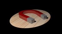
Magnet
...magnet 3docean 3d 3ds max electric magnet magnetic magnetism max model polygon realistic tesla magnet created in...
turbosquid
$6
Magnet
...
turbosquid
royalty free 3d model magnet for download as obj on turbosquid: 3d models for games, architecture, videos. (1548733)
turbosquid
$6

magnet
...uid
royalty free 3d model magnet for download as 3dm and max on turbosquid: 3d models for games, architecture, videos. (1670606)
turbosquid
$1

Magnet
...y free 3d model magnet for download as 3ds, max, obj, and fbx on turbosquid: 3d models for games, architecture, videos. (1215037)
turbosquid
$7

Magnet
...agnet for download as blend, unitypackage, fbx, gltf, and obj on turbosquid: 3d models for games, architecture, videos. (1576588)
3d_export
$5
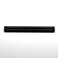
magnetic knife holder
...magnetic knife holder
3dexport
ordinary magnetic knife holder
archive3d
free

Fridge magnet 3D Model
...3d model archive3d refrigerator magnet fridge magnet magnet toy magnetic s n280712 - 3d model (*.3ds) for interior 3d...
turbosquid
$35

Magnetic butterflies
...alty free 3d model magnetic butterflies for download as blend on turbosquid: 3d models for games, architecture, videos. (1315792)
turbosquid
$2
Magnetic Board
...quid
royalty free 3d model magnetic board for download as ma on turbosquid: 3d models for games, architecture, videos. (1264141)
turbosquid
$977

Magnetic Lego
...oyalty free 3d model magnetic lego for download as ma and obj on turbosquid: 3d models for games, architecture, videos. (1142761)
Electric
3d_export
$5

Electric pole
...electric pole
3dexport
electric pole for street, electricity line
3ddd
$1
electric mixer
...electric mixer
3ddd
electric mixer , миксер
electric mixer
3ddd
$1

electrical installation
...electrical installation
3ddd
electrical installation , розетка
electrical installation
turbosquid
$19
The electric water heater electric
... available on turbo squid, the world's leading provider of digital 3d models for visualization, films, television, and games.
turbosquid
free
Electrical Outlet electric splitter
... available on turbo squid, the world's leading provider of digital 3d models for visualization, films, television, and games.
3d_ocean
$20

Electric Guitar
...electric guitar
3docean
electric electric guitar guitar music music instrument
model of a electric guitar created in maya.
3d_ocean
$12

Electric Shaver
...electric shaver
3docean
electric electric shaver hair removal personal care shaver shaving
electric shaver created in 3ds max.
3ddd
$1

electrical switch
...h
3ddd
electrical , розетка
electrical switch from bticino company
series livinglight
3d_export
$7
Electric Conveyor
...electric conveyor
3dexport
electric conveyor
3d_export
$5

electric drums
...electric drums
3dexport
electric drums
Generator
3d_export
$17

Generator
...generator
3dexport
generator
archibase_planet
free

Generator
...base planet
generator electric generator
generator electric n300715 - 3d model (*.gsm+*.3ds+*.max) for interior 3d visualization.
design_connected
$20

Generation
...generation
designconnected
knoll generation computer generated 3d model. designed by formway design.
3d_export
$8

generator
...generator
3dexport
generator - obj, 3ds, fbx.
3d_export
$7

generator
...generator
3dexport
generator extures 4k resolution, basecolor -normal -metallic -ao-roughness-height tris:3084
turbosquid
free

generator
...rator
turbosquid
free 3d model generator for download as max on turbosquid: 3d models for games, architecture, videos. (1492909)
3ddd
$1

general
...general
3ddd
генерал
turbosquid
$99

generator
...urbosquid
royalty free 3d model generator for download as ma on turbosquid: 3d models for games, architecture, videos. (1514125)
turbosquid
$20

Generator
...rbosquid
royalty free 3d model generator for download as max on turbosquid: 3d models for games, architecture, videos. (1244841)
turbosquid
$2

Generator
...rbosquid
royalty free 3d model generator for download as fbx on turbosquid: 3d models for games, architecture, videos. (1245541)