Thingiverse
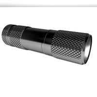
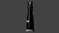
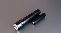
LED Rechargeable Flashlight (V2) by cyamate
by Thingiverse
Last crawled date: 3 years ago
Update 3/25/18 Recieved my high efficency LED's and did a bit of testing: with a 2850mah tested cell, charge time 3.5hours discharge on High Setting(1400ma) 2.5 hours, discharge on medium setting 9hours!!
Update 3/17/18 added a new file for the shell that has a cone of support to help print the very tall slender body. End Update.
Update 3/3/2018
This is an update to post my V2 of this awesome project. I have changed some purchased components to make this flashlight more reliable, but I haven't yet received my new LED's, yet so the testing results are still TBD.
This Build is slightly more expensive, but the good news is I have made it mostly able to be disassembled, you still need to epoxy the board and solder all connections but other than that, it comes apart! very cool.
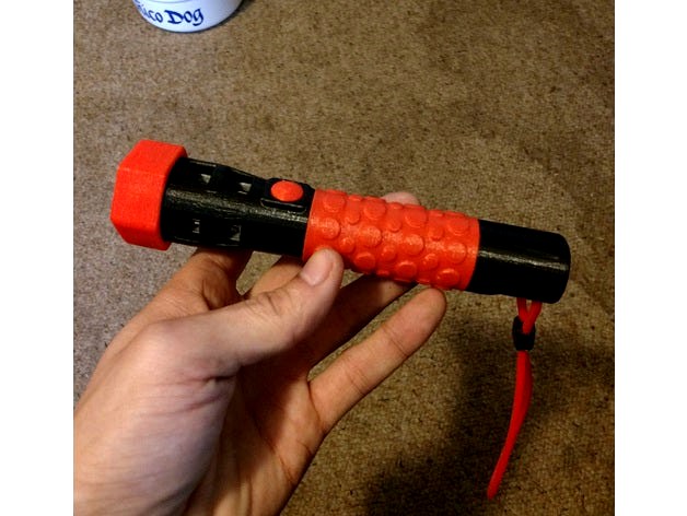
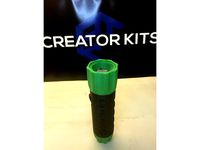
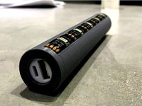
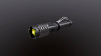
other features updated: Adjustable beam angle, Recharge indicator viewing hole, more than 200% the heat sink thermal mass and surface area, smaller button, flex grip handle and lanyard, easier wiring and assembly.
Updated Purchased Parts:
The only three changes to the below Bill of Materials are the LED, LED Driver Board and more copper heat sinks. I chose Cree's most efficient LED line, the XP-E2 r4 mounted to a Noctigon 16mm copper MCPCB (https://intl-outdoor.com/noctigon-xp16-mcpcb-cree-xpe2-r4-1a-led-p-772.html) These LED's are rated for 1A but after research I found that they can be overclocked by 300% safely (just a lot of heat to get rid of) so I chose to run 1.4A boards with 3 or 5 modes. (https://www.fasttech.com/p/1122401) these will also serve as your lights under voltage protection device. Lastly you need these large copper heat sinks as well as the smaller ones listed below. (http://a.co/ae0EfHE)
Updated printed parts
To be safe please redownload all files and delete your old ones. Small changes were made to V1 parts. In order to print this V2 you must be able to print flexible materials!! The lens is held by the hex cover to make it an adjustable beam.
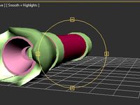
Two heat sinks must be soldered together as shown in the renderings and the heat sink soldered directly to the MCPCB if your using aluminum you have to use the thermal adhesive pads that come with the sinks.
I have left the V1 STLs up so be careful to choose the right files to print.
No need to glue the button down, it is held in place by the soldered wires
No need to glue the heat sinks in, they are held in by the wires, epoxy if you want to.
End Update 3/3/2018
Here is the Version 1 of my Flashlight design. This is a slightly advanced maker project due to the tight soldering and various printing materials. You must be able to print ABS at the very least, NinjaFlex if you want to use the soft button and hex lens cover.
This project is worthwhile if you want to make many flashlights as gifts and such because many of the components are sold in packs of 10 for cost effectiveness.
Caution! The way that these components work together, the highest setting will Burn out the LED at Full Battery Charge!!! I use the lowest setting mostly and even then the heat sink gets pretty hot after a while.
Warning! the Copper heat sink is exposed for cooling purposes and can become very hot. yes I have slightly burned my self sticking my pinky finger in the hole to see how hot it was. It's hot!
List of Purchased Components
18mm Acrylic Convex Lens (2 packs/ $0.51ea) https://www.fasttech.com/p/4539801
16mm LED Driver (10packs/ $1.15ea) https://www.ebay.com/i/251690022903?chn=ps&fl=a
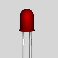
16mm Cree XM-L LED T6 White (1, 5, 10 packs/ $1.88ea) https://www.ebay.ca/itm/10W-Cree-Single-Die-XM-L-LED-T6-White-1040Lm-3000mA-led-chip-16mm-20mm-pcb-F-DIY-/322153245872
Micro USB TP4056 18650 Lithium Battery Charger Module (5 packs, $1.40ea) http://a.co/8y4FERs
18650 Lithium Cell - I have a bunch so I dont have a specific link (~$2.00-$5.00/ea)
Self Locking Micro Switch (6 packs/ $0.75ea) https://www.ebay.ca/itm/6-Pieces-Black-Latching-self-locking-1A-push-button-on-off-micro-mini-1208-YD-B5/252946680354?hash=item3ae4cc0a22:g:s14AAOSwfpVZHsGH
Mosfet Passive Heat Sink 10x10x14mm, Copper (10packs/ $2.00ea) http://a.co/ertOrNt
Total cost of one Flashlight = ~$10.00 + Printed Parts + You're invaluable Time.
Print All core pieces out of ABS or your preferred high strength high temp resistant material. -Print all pieces standing on end with a 0.4mm nozzle @0.2mm/lyr (recommended large brim)
Print the Shell in any material you want, vertically with charger hole down
-Support everything to 55-60° overhang @ 20% zigzag
I print ninjaflex at 240°C and 8mm/sec speed everywhere. (you have to run a lot of material thru before you push out the last of what ever was in the nozzle before. Just keep trying)
Assembly
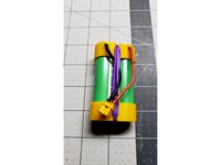
1) Solder a very short lead from the out(-) on the charger module directly to the negative side of the 18650 Cell. Make sure not to install the board too close to the battery, it could short if done wrong. I added a drop of epoxy once assembled to keep the board separated from the battery.
2) Solder a longer lead from the out(+) on the charger module directly to the positive end of the 18650 Cell. This lead should be just long enough to reach, so cut it to length and strip. the wire has to fit in the groove of the battery holder piece so make sure all support or print bumps are eliminated in this groove.
3) Solder a 5 inch lead to the same place as the out(-) on the negative side of the battery. This lead also has to fit into the groove on the battery holder so use thin wires. I used 24 AWG solid for these wires. this wire will go to one side of the switch, doesn't matter witch side.
4) Solder a short flexible length of wire to the same place on the positive battery terminal. place the battery and charger into the battery holder piece. as you slide the battery into place, guide the negative wire out the bottom and the positive wire through the end
5) Epoxy Charge board to the battery holder such that the charger port is flush with the end of the flat plate. Use the same batch of epoxy to ensure the board stays separated from the battery. Clamp lightly in place while adhesive cures. Glue the battery in place if you want to as well. I didn't.
6) Solder the positive wire that is sticking out of the end of the battery holder part to the center plate on the back side of the LED Driver module. Make sure that the LED Driver is totally round by trimming it with a rotary tool. I will not fit otherwise.
7) Solder a 2 inch lead to the outside ring on the back of the LED Driver. This wire will also go to the switch and will be trimmed to length when soldering in the switch.
8) Push the LED Driver into the end of the Battery Holder making sure not to break the connections you've made. The LED Driver Board should be flush with the rim of the end.
9) De-solder the leads from the LED Driver making note witch side was positive and negative. Bend the tips of the leads and hook them thru the notches on the CREE LED and solder them to the LED.
10) Using the provided adhesive patches that came with the Copper Heat Sinks, attach the sink as square and center as possible on the back of the led. this is important to make sure the led is straight, use the break lines on the top and bottom as alignment tools. you can place and replace if your careful. then press it on hard when you've got a good position. Don't bend the copper pin fins.
11)make sure that the Sink fits into the LED Holder part and the leads are only sticking out a short amount before gluing it in place. I epoxied the inside of the four support pillars to the corner pins. Press the assembled LED and Sink into place
12) epoxy the lens into the LED holder, there is a step that will not let it go too far. make sure the Lens is clean to your liking, it will not be removable. nothing is really.
13) Test the polarity of the LED and LED Driver by touching the switch wires together and carefully setting the two leads of the led to where the wires were originally soldered. if no light, try the reverse polarity. once it flashes make note of the polarity.
14) making sure the switch leads are not touching, solder the LED leads to the LED driver. Twist the wires slightly so that the LED Holder and Battery Holder come together (don't glue yet). you can continue testing the connections by touching the switch wires together.
15) making sure that the locking button is depressed (off) epoxy it into place and solder the switch leads to it, polarity doesn't matter for mechanical switches. Continue testing the light but don't leave it on for more than a short moment.
16) Make sure that the Shell part is clear of debris inside. Test fitting before electrical assembly is recommended.
17) Epoxy the LED Holder part to the Battery holder part and quickly insert the entire core assembly into the Shell part and press it all into place. the switch button should appear centered in the button hole.
18) Epoxy edge of bottom of flexible button to the flat spots exposed to the button hole.
Now you've got a homemade 3d printed LED Flashlight!
I cant stress enough not to use the high setting for more than .25 seconds. the light will turn bluish and you WILL burn out the LED. This Flashlight was not meant to be taken apart for repair, unless you can manage to assemble it that way.
I look forward to seeing your makes! That is if you get this made successfully. please let me know in the comments what you think and how it could be improved. I will be working on a bike light that uses an external portable battery pack.
Good Luck and Happy Printing!
Update 3/17/18 added a new file for the shell that has a cone of support to help print the very tall slender body. End Update.
Update 3/3/2018
This is an update to post my V2 of this awesome project. I have changed some purchased components to make this flashlight more reliable, but I haven't yet received my new LED's, yet so the testing results are still TBD.
This Build is slightly more expensive, but the good news is I have made it mostly able to be disassembled, you still need to epoxy the board and solder all connections but other than that, it comes apart! very cool.
other features updated: Adjustable beam angle, Recharge indicator viewing hole, more than 200% the heat sink thermal mass and surface area, smaller button, flex grip handle and lanyard, easier wiring and assembly.
Updated Purchased Parts:
The only three changes to the below Bill of Materials are the LED, LED Driver Board and more copper heat sinks. I chose Cree's most efficient LED line, the XP-E2 r4 mounted to a Noctigon 16mm copper MCPCB (https://intl-outdoor.com/noctigon-xp16-mcpcb-cree-xpe2-r4-1a-led-p-772.html) These LED's are rated for 1A but after research I found that they can be overclocked by 300% safely (just a lot of heat to get rid of) so I chose to run 1.4A boards with 3 or 5 modes. (https://www.fasttech.com/p/1122401) these will also serve as your lights under voltage protection device. Lastly you need these large copper heat sinks as well as the smaller ones listed below. (http://a.co/ae0EfHE)
Updated printed parts
To be safe please redownload all files and delete your old ones. Small changes were made to V1 parts. In order to print this V2 you must be able to print flexible materials!! The lens is held by the hex cover to make it an adjustable beam.
Two heat sinks must be soldered together as shown in the renderings and the heat sink soldered directly to the MCPCB if your using aluminum you have to use the thermal adhesive pads that come with the sinks.
I have left the V1 STLs up so be careful to choose the right files to print.
No need to glue the button down, it is held in place by the soldered wires
No need to glue the heat sinks in, they are held in by the wires, epoxy if you want to.
End Update 3/3/2018
Here is the Version 1 of my Flashlight design. This is a slightly advanced maker project due to the tight soldering and various printing materials. You must be able to print ABS at the very least, NinjaFlex if you want to use the soft button and hex lens cover.
This project is worthwhile if you want to make many flashlights as gifts and such because many of the components are sold in packs of 10 for cost effectiveness.
Caution! The way that these components work together, the highest setting will Burn out the LED at Full Battery Charge!!! I use the lowest setting mostly and even then the heat sink gets pretty hot after a while.
Warning! the Copper heat sink is exposed for cooling purposes and can become very hot. yes I have slightly burned my self sticking my pinky finger in the hole to see how hot it was. It's hot!
List of Purchased Components
18mm Acrylic Convex Lens (2 packs/ $0.51ea) https://www.fasttech.com/p/4539801
16mm LED Driver (10packs/ $1.15ea) https://www.ebay.com/i/251690022903?chn=ps&fl=a
16mm Cree XM-L LED T6 White (1, 5, 10 packs/ $1.88ea) https://www.ebay.ca/itm/10W-Cree-Single-Die-XM-L-LED-T6-White-1040Lm-3000mA-led-chip-16mm-20mm-pcb-F-DIY-/322153245872
Micro USB TP4056 18650 Lithium Battery Charger Module (5 packs, $1.40ea) http://a.co/8y4FERs
18650 Lithium Cell - I have a bunch so I dont have a specific link (~$2.00-$5.00/ea)
Self Locking Micro Switch (6 packs/ $0.75ea) https://www.ebay.ca/itm/6-Pieces-Black-Latching-self-locking-1A-push-button-on-off-micro-mini-1208-YD-B5/252946680354?hash=item3ae4cc0a22:g:s14AAOSwfpVZHsGH
Mosfet Passive Heat Sink 10x10x14mm, Copper (10packs/ $2.00ea) http://a.co/ertOrNt
Total cost of one Flashlight = ~$10.00 + Printed Parts + You're invaluable Time.
Print All core pieces out of ABS or your preferred high strength high temp resistant material. -Print all pieces standing on end with a 0.4mm nozzle @0.2mm/lyr (recommended large brim)
Print the Shell in any material you want, vertically with charger hole down
-Support everything to 55-60° overhang @ 20% zigzag
I print ninjaflex at 240°C and 8mm/sec speed everywhere. (you have to run a lot of material thru before you push out the last of what ever was in the nozzle before. Just keep trying)
Assembly
1) Solder a very short lead from the out(-) on the charger module directly to the negative side of the 18650 Cell. Make sure not to install the board too close to the battery, it could short if done wrong. I added a drop of epoxy once assembled to keep the board separated from the battery.
2) Solder a longer lead from the out(+) on the charger module directly to the positive end of the 18650 Cell. This lead should be just long enough to reach, so cut it to length and strip. the wire has to fit in the groove of the battery holder piece so make sure all support or print bumps are eliminated in this groove.
3) Solder a 5 inch lead to the same place as the out(-) on the negative side of the battery. This lead also has to fit into the groove on the battery holder so use thin wires. I used 24 AWG solid for these wires. this wire will go to one side of the switch, doesn't matter witch side.
4) Solder a short flexible length of wire to the same place on the positive battery terminal. place the battery and charger into the battery holder piece. as you slide the battery into place, guide the negative wire out the bottom and the positive wire through the end
5) Epoxy Charge board to the battery holder such that the charger port is flush with the end of the flat plate. Use the same batch of epoxy to ensure the board stays separated from the battery. Clamp lightly in place while adhesive cures. Glue the battery in place if you want to as well. I didn't.
6) Solder the positive wire that is sticking out of the end of the battery holder part to the center plate on the back side of the LED Driver module. Make sure that the LED Driver is totally round by trimming it with a rotary tool. I will not fit otherwise.
7) Solder a 2 inch lead to the outside ring on the back of the LED Driver. This wire will also go to the switch and will be trimmed to length when soldering in the switch.
8) Push the LED Driver into the end of the Battery Holder making sure not to break the connections you've made. The LED Driver Board should be flush with the rim of the end.
9) De-solder the leads from the LED Driver making note witch side was positive and negative. Bend the tips of the leads and hook them thru the notches on the CREE LED and solder them to the LED.
10) Using the provided adhesive patches that came with the Copper Heat Sinks, attach the sink as square and center as possible on the back of the led. this is important to make sure the led is straight, use the break lines on the top and bottom as alignment tools. you can place and replace if your careful. then press it on hard when you've got a good position. Don't bend the copper pin fins.
11)make sure that the Sink fits into the LED Holder part and the leads are only sticking out a short amount before gluing it in place. I epoxied the inside of the four support pillars to the corner pins. Press the assembled LED and Sink into place
12) epoxy the lens into the LED holder, there is a step that will not let it go too far. make sure the Lens is clean to your liking, it will not be removable. nothing is really.
13) Test the polarity of the LED and LED Driver by touching the switch wires together and carefully setting the two leads of the led to where the wires were originally soldered. if no light, try the reverse polarity. once it flashes make note of the polarity.
14) making sure the switch leads are not touching, solder the LED leads to the LED driver. Twist the wires slightly so that the LED Holder and Battery Holder come together (don't glue yet). you can continue testing the connections by touching the switch wires together.
15) making sure that the locking button is depressed (off) epoxy it into place and solder the switch leads to it, polarity doesn't matter for mechanical switches. Continue testing the light but don't leave it on for more than a short moment.
16) Make sure that the Shell part is clear of debris inside. Test fitting before electrical assembly is recommended.
17) Epoxy the LED Holder part to the Battery holder part and quickly insert the entire core assembly into the Shell part and press it all into place. the switch button should appear centered in the button hole.
18) Epoxy edge of bottom of flexible button to the flat spots exposed to the button hole.
Now you've got a homemade 3d printed LED Flashlight!
I cant stress enough not to use the high setting for more than .25 seconds. the light will turn bluish and you WILL burn out the LED. This Flashlight was not meant to be taken apart for repair, unless you can manage to assemble it that way.
I look forward to seeing your makes! That is if you get this made successfully. please let me know in the comments what you think and how it could be improved. I will be working on a bike light that uses an external portable battery pack.
Good Luck and Happy Printing!
Similar models
thingiverse
free
High Output LED Flashlight by Rauch
...uper glue. the heat generated by the led will vaporize super glue and create a cloudy coating on the led, optics and lens cover.
thingiverse
free

Simple LED Flashlight by ALABS
...on in the square cutout in the acrylic window.
snap the window onto the enclosure.
put batteries in the battery holder and enjoy!
thingiverse
free
Teal 9V, 10W power LED cover by toymulders
...ta scheet to make sure you attach the wires the the wright side)
test the light
does it work?
then you are ready to start flying
thingiverse
free
Bathroom joule thief night light by ER05ONE
... if all ok, secure components with a bit of hot glue or epoxy.
fit lid.
tip: use blue tac to hold your components when soldering.
thingiverse
free
heat pro repman heater for preventing warping. by jamesvilleneuve
..., and the pcb acts as a good stick layer for thermal plastic. i also have a video here:http://www.youtube.com/watch?v=pdekp3ym1te
thingiverse
free
full printed flashlight for 18650 battery by denmx
...y by denmx
thingiverse
scale 1:1.
for this thing you also need:
led 1-3w with driver
battery 18650
push button
silver paint
wire
thingiverse
free
18650 holder 1S / 2S
...make sure they are correctly oriented. 1s instructions follow similar steps as described in the2s construction, however: solder two...
thingiverse
free
Portable Ambient Light LED Powerbank by vmi
...te controller 5v
single 18650 diy powerbank
18650 li-ion battery
22mm switch
wire
soldering iron
glue
heat shrink tube
multimeter
thingiverse
free
Flashlight Housing by lanceve
...uncomfortable to use for any significant duration. the completed board can be slid into this housing for more comfortable usage.
thingiverse
free
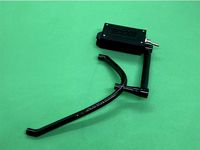
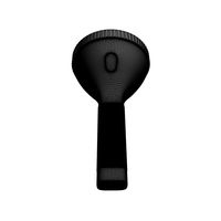
TrackIR TrackClip PRO Battery Compartment Headphones Clip by falken_gt4
...der the red wire to the leds to the other terminal on the switch.
4) make sure to insulate properly, i used heat shrink sleeving.
Cyamate
thingiverse
free
Massage Bump by cyamate
...sage bump by cyamate
thingiverse
find a place to put this opposite of your tv and work out some knots.
nothing much more to say.
thingiverse
free

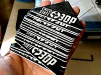
Raiders Three Tone Logo by cyamate
... three tone logo by cyamate
thingiverse
this is a three color print. try and time the color switching right. or dont, whatever
thingiverse
free
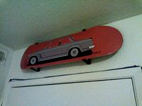
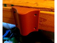
Skateboard Wall Mount (no trucks) by cyamate
...nting a 8" wide skateboard 3" away from the wall so the tip and tail dont touch the wall. needed these so i drew them.
thingiverse
free
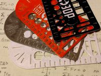
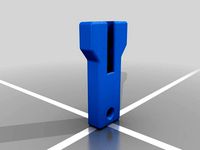
Drawing Template (Chico State 3DP Club) by cyamate
...is a design i created as a giveaway to advertise the chico state club on campus. print this in abs with a very slow base layer.
thingiverse
free
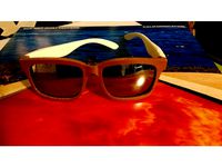
Sunglasses by cyamate
...your makes, thanks everyone!!
for best results, print the main frame in abs and the arms in pla. don't leave them in the car!
thingiverse
free
Tabletop Football (Chico State 3DP) by cyamate
... designed these as a giveaway for our 3d printing club at chico state. i may change the laces to be cut out instead of embossed.
thingiverse
free
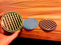
Perfect Coaster by cyamate
... and slow your printer down to 10% and change the color. i made three and they look pretty cool. the green and black one is v3.
thingiverse
free
SF Giants Logo by cyamate
... as i would have hoped. but if you get the right colors it should look great!!
color switching order: wood, white, black, orange
thingiverse
free
Chico State 3DP Flex Bracelet by cyamate
...eone wearing one!! :) ... "he makes jewelry now..." portlandia quote
print with ninja flex or equivalent tpe plastic
cy
thingiverse
free
INCUBUS (crow left of a murder) LOGO with birdies by cyamate
... i don't know if all the lines show up when you reduce the size. make it your own with any color combination you'd like.
Rechargeable
3d_export
free
rechargeable battery
...rechargeable battery
3dexport
rechargeable battery(name"tornado")
turbosquid
$10
Rechargeable Drill
... available on turbo squid, the world's leading provider of digital 3d models for visualization, films, television, and games.
3d_export
$5
portable and rechargeable uv light sterilizer
...portable and rechargeable uv light sterilizer
3dexport
portable and rechargeable uv light sterilizer
3d_export
$69
Volvo C40 Recharge
...vertisements or games corona render and materials all textures include in *.rar files lighting setup is not included in the file!
3d_export
$99
Volvo C30 Recharge Concept 3D Model
...e re-charge 2007 2008 2009 concept future car electric eco sweden swedish
volvo c30 recharge concept 3d model squir 5344 3dexport
3d_ocean
$15
Fairly Aged Rusty Rechargeable Lamp
... model, abandoned lighting. great furniture. includes file format for element 3d. available format obj. 3ds. c4d. low poly files.
cg_studio
$99
Volvo c30 ReCharge Concept3d model
...
.3ds .lwo .max .obj .xsi - volvo c30 recharge concept 3d model, royalty free license available, instant download after purchase.
turbosquid
$10
Accu charger - Battery - Powerbank - rechargeable
... available on turbo squid, the world's leading provider of digital 3d models for visualization, films, television, and games.
3d_export
$8
rechargeable table fan
...nimated or replaced. all textured are applied with high quality with 2k resolution. please share your experience with this model.
3d_export
$69

VOLVO XC40 Recharge 2023
...>corona render and materials<br>all textures include in *.rar files<br>lighting setup is not included in the file!
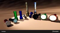
Flashlight
3d_export
$5

Flashlight
...flashlight
3dexport
flashlight
3d_ocean
$6
Flashlight
...flashlight
3docean
beam flashlight light
hello! is pleased to present you my new project-flashlight
3d_export
free
Flashlight
...flashlight
3dexport
the most common portable flashlight.
3d_export
$10
flashlight
...flashlight
3dexport
3d model of a flashlight for horror video games or other
3d_export
$15
flashlight
...flashlight
3dexport
low poly model - flashlight, modeling in blender, texturing in substance painter
turbosquid
$2
Flashlight
...squid
royalty free 3d model flashlight for download as blend on turbosquid: 3d models for games, architecture, videos. (1686591)
turbosquid
$1

Flashlight
...squid
royalty free 3d model flashlight for download as blend on turbosquid: 3d models for games, architecture, videos. (1434506)
turbosquid
$10
Flashlights
...ree 3d model flashlights for download as fbx and unitypackage on turbosquid: 3d models for games, architecture, videos. (1286431)
turbosquid
free
Flashlight
...
royalty free 3d model flashlight for download as max and obj on turbosquid: 3d models for games, architecture, videos. (1272424)
turbosquid
$10
Flashlight
... free 3d model flashlight for download as blend, max, and obj on turbosquid: 3d models for games, architecture, videos. (1518564)
V2
3d_export
free
Lamp v2
...lamp v2
3dexport
lamp v2 with solar panel
3d_export
$5
hammerhead v2
...hammerhead v2
3dexport
razer hammerhead v2 headphones, modeled in cinema 4d, render in corona
3d_export
$5
manometer v2
...manometer v2
3dexport
3d_export
$5
potato v2
...potato v2
3dexport
turbosquid
$52
Lifebuoys v2
...squid
royalty free 3d model lifebuoys v2 for download as fbx on turbosquid: 3d models for games, architecture, videos. (1560870)
turbosquid
$2

Mask v2
...turbosquid
royalty free 3d model mask v2 for download as stl on turbosquid: 3d models for games, architecture, videos. (1527741)
turbosquid
$20
Kitchen V2
...ty free 3d model kitchen v2 for download as max, obj, and fbx on turbosquid: 3d models for games, architecture, videos. (1155111)
turbosquid
$20

kengkod64-v2
... free 3d model kengkod64-v2 for download as 3dm, ztl, and stl on turbosquid: 3d models for games, architecture, videos. (1701415)
turbosquid
$19
Chair v2
...yalty free 3d model chair v2 for download as ma, obj, and fbx on turbosquid: 3d models for games, architecture, videos. (1693360)
turbosquid
$15
Table v2
...yalty free 3d model table v2 for download as ma, fbx, and obj on turbosquid: 3d models for games, architecture, videos. (1688743)
Led
3d_export
$5
led
...led
3dexport
the led is cut with all the parts.
3ddd
$1
Monacor / PARL56DMX / LED-320RGBW / LED-345RGBW / LED-300RGB
... прожектор
http://www.monacor.dk/
parl56dmx
led-320rgbw
led-345rgbw
led-300rgb
turbosquid
$10
LED
...led
turbosquid
free 3d model led for download as blend on turbosquid: 3d models for games, architecture, videos. (1691856)
3d_export
$5
led lamp
...led lamp
3dexport
led lamp, brightness animation
3ddd
free
leds-c4
...leds-c4
3ddd
leds-c4
современный торшер
3ddd
free
leds-c4
...leds-c4
3ddd
leds-c4
настольный лампа
turbosquid
$19
LED
... available on turbo squid, the world's leading provider of digital 3d models for visualization, films, television, and games.
turbosquid
$12
Led
... available on turbo squid, the world's leading provider of digital 3d models for visualization, films, television, and games.
turbosquid
free
LED
... available on turbo squid, the world's leading provider of digital 3d models for visualization, films, television, and games.
turbosquid
free
LED
... available on turbo squid, the world's leading provider of digital 3d models for visualization, films, television, and games.