Thingiverse
ISS and LEO satellites tracker by f2knpw
by Thingiverse
Last crawled date: 3 years, 3 months ago
Let's start by two video of a real ISS tracking in my home :)
One at 16x speed and one much longer but with explainations !https://youtu.be/MYff_J85vZohttps://youtu.be/_7pX7NHbo6A
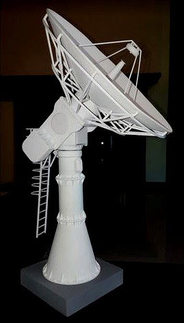
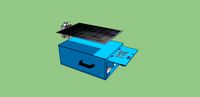
So here is a mockup of a ground station antenna, able to track any LEO sat you want.
The antenna is 3D printed from a design I made starting with a 6 meter dish antenna picture.
The dish is now 20cm wide, has a real paraboloid shape and is moved by two stepper motors fully hidden into the pedestal of the antenna.
Two hall effect sensors and two magnets allow to setup the antenna horizontal and pointing to north at boot time. They are also hidden into the structure.
An ESP32 is also hidden in the basement and is the heart of the system. It computes the position of the satellites every 1ms and computes the azimuth and elevation angles from your antenna to the satellite.
An android App allows to visualize the track and to send parameters to the antenna : which satellites to follow, the Two Lines Elements and the time.https://www.b4x.com/android/forum/threads/iss-and-leo-satellites-tracker.123325/
The orbit propagator is embeded in the ESP32 and uses the excellent SGP4 library ported by hopperpop ! https://github.com/Hopperpop/Sgp4-Library
the firmware was directly inspired by Alex Chang project : (Thanls Alex for sharing ) https://create.arduino.cc/projecthub/alex_chang/satellite-tracker-13a9aa
How to do it :
see all details in SatTracker_howTo.pdf
Source code available for lite version :ESP32_SatTracker_lite.zip
Print the dish in two halves (brim may help !).
Then glue both parts with epoxy glue.
Sand, fill, re sand and paint it.
print the support and twelve elements of the "umbrella"
Glue the dish in place and center it into its base
add the horn and its supports (beware they are fragile)
add also the two rings into the slots to finish the dish
print the three pieces of the foot but don't glue them together now. It will be easier to glue them when te whole ntenna will be finished !
Then print the azimuth shaft parts and use a 3mm leadscrew as the shaft. see stl template for the lenght.
The motors wires are slided into the roller ball bearing axis, so that they won't tangle when the antenna rotates
the dish weights around 120 g. This must be balanced by counterweights on the other side of the antenna.
Note that the counterweight is half the weight of the antenna dish and made with lead molten into a metal shape of the plastic counterweight. This is absolutely needed to keep the antenna balanced, as the dish weights 120g... So 60g of lead on each side, thus a total of 240g. Just small enough for the motor to be able to move all this !
don't forget to add a 2mm magnet into one of the counterweights. It will be used to calibrate the elvation motor. It mut be glue into the side which does NOT have the shape of the motor shaft.
do the same in the foot of the antenna for the azimuth axis calibration.
When everything in place, glue with epoxy to seal the counterweights.
Then add pieces of PLA filament to help you center the counterweights on the dish and glue all this in place.
The two hall sensor and magnets must be put placed in way that the hall switch acts (closes) when the magnet is close to the sensor. If this does not happend, then simply rotates the magnet !
the motor has been modified to switch it to bipolar (to increase torque). Modification is explained here : https://www.thingiverse.com/thing:3746391
I use two "easysteppers" drivers to drive the motors. They are cheap and easy to find on ebay or aliexpress. Simple wiring, no extra jumper needed !
One at 16x speed and one much longer but with explainations !https://youtu.be/MYff_J85vZohttps://youtu.be/_7pX7NHbo6A
So here is a mockup of a ground station antenna, able to track any LEO sat you want.
The antenna is 3D printed from a design I made starting with a 6 meter dish antenna picture.
The dish is now 20cm wide, has a real paraboloid shape and is moved by two stepper motors fully hidden into the pedestal of the antenna.
Two hall effect sensors and two magnets allow to setup the antenna horizontal and pointing to north at boot time. They are also hidden into the structure.
An ESP32 is also hidden in the basement and is the heart of the system. It computes the position of the satellites every 1ms and computes the azimuth and elevation angles from your antenna to the satellite.
An android App allows to visualize the track and to send parameters to the antenna : which satellites to follow, the Two Lines Elements and the time.https://www.b4x.com/android/forum/threads/iss-and-leo-satellites-tracker.123325/
The orbit propagator is embeded in the ESP32 and uses the excellent SGP4 library ported by hopperpop ! https://github.com/Hopperpop/Sgp4-Library
the firmware was directly inspired by Alex Chang project : (Thanls Alex for sharing ) https://create.arduino.cc/projecthub/alex_chang/satellite-tracker-13a9aa
How to do it :
see all details in SatTracker_howTo.pdf
Source code available for lite version :ESP32_SatTracker_lite.zip
Print the dish in two halves (brim may help !).
Then glue both parts with epoxy glue.
Sand, fill, re sand and paint it.
print the support and twelve elements of the "umbrella"
Glue the dish in place and center it into its base
add the horn and its supports (beware they are fragile)
add also the two rings into the slots to finish the dish
print the three pieces of the foot but don't glue them together now. It will be easier to glue them when te whole ntenna will be finished !
Then print the azimuth shaft parts and use a 3mm leadscrew as the shaft. see stl template for the lenght.
The motors wires are slided into the roller ball bearing axis, so that they won't tangle when the antenna rotates
the dish weights around 120 g. This must be balanced by counterweights on the other side of the antenna.
Note that the counterweight is half the weight of the antenna dish and made with lead molten into a metal shape of the plastic counterweight. This is absolutely needed to keep the antenna balanced, as the dish weights 120g... So 60g of lead on each side, thus a total of 240g. Just small enough for the motor to be able to move all this !
don't forget to add a 2mm magnet into one of the counterweights. It will be used to calibrate the elvation motor. It mut be glue into the side which does NOT have the shape of the motor shaft.
do the same in the foot of the antenna for the azimuth axis calibration.
When everything in place, glue with epoxy to seal the counterweights.
Then add pieces of PLA filament to help you center the counterweights on the dish and glue all this in place.
The two hall sensor and magnets must be put placed in way that the hall switch acts (closes) when the magnet is close to the sensor. If this does not happend, then simply rotates the magnet !
the motor has been modified to switch it to bipolar (to increase torque). Modification is explained here : https://www.thingiverse.com/thing:3746391
I use two "easysteppers" drivers to drive the motors. They are cheap and easy to find on ebay or aliexpress. Simple wiring, no extra jumper needed !
Similar models
grabcad
free

Satellite tracker concept
... concept
grabcad
conceptual design of a alt-azimuth configuration satellite tracker. it can be also be used as a radiotelescope.
grabcad
free

Magnetic Loop Antenna for HF band
...ct ontrolled by arduino esp32 and stepper motor
... under costruction ....
some part 3d printed to realize magnetic loop antenna
thingiverse
free

Track Occupancy sensor (Trackside Cabinet) by dagnall53
...:wio-en&s[]=wio)
this video shows the original version running different software.https://www.youtube.com/watch?v=c6bxuhb6rpu
cg_trader
free

Satellite antenna or dish
...satellite antenna or dish
cg trader
satellite antenna or dish antenna dish satellite metal electronics satellite dish other
thingiverse
free

Thrustmaster T-Flight Hotas X Joystick - Hall Effect Conversion by t_teeds
...at 90 degrees to it. use hot glue or similar to fix the sensor and wires in place on...
free3d
free

Satellite Antenna Dish
...satellite antenna dish
free3d
satellite antenna dish.
grabcad
free

Satellite antenna or dish
...satellite antenna or dish
grabcad
satellite antenna or dish
3d_sky
$8

KU BAND satellite dish
...tellite antenna
ku band 60 cm material: steel
diameter: 60 cm
variatnami-with two mounting to horizontal and vertical surfaces.
3d_sky
free

Satellite dish
...satellite dish
3dsky
dish satellite antenna satellite dish
detailed model of the satellite dish.
thingiverse
free

OWI ISS Tracker by Stevorino21
...iss tracker by stevorino21
thingiverse
owi parts to remove dc motors, remove and disable certain joints, and add stepper motors.
F2Knpw
thingiverse
free

USB cable repair by f2knpw
...usb cable repair by f2knpw
thingiverse
prints in two parts
then glue with cyanoacrylate glue
thingiverse
free

Enclosure spool holder by f2knpw
...enclosure spool holder by f2knpw
thingiverse
just two feet for enclosure spool holder.
works with the roll holder here :
thingiverse
free

Logitech webcam holder. by f2knpw
...der. by f2knpw
thingiverse
a very simple webcam holder.
designed for logitech 200
allows to fix a tripod with standard 6mm screw
thingiverse
free

HTC One Mini2 tripod holder by f2knpw
...unt for htc one mini2
almost invisible, but fits nicely on the edges.
just screw the tripod into the 6 mm hole to make threadings
thingiverse
free

Windmeter for Android by f2knpw
...alibrate the speed using the gps and display it on a gauge.
well, see it into action :https://www.youtube.com/watch?v=ja16slseuum
thingiverse
free

Lora 868 MHz dipole antenna by f2knpw
...frequency
more information here : https://github.com/congducpham/tutorials/blob/master/low-cost-lora-iot-outdoor-step-by-step.pdf
thingiverse
free

AS5600 encoder holder for NEMA17 stepper motor by f2knpw
... be used with a nema17 motor.
details here : https://community.simplefoc.com/t/simplefoclibrary-support-for-stepper-motors/137/42
thingiverse
free

Original Prusa i3 MK2s filament dust cleaner by f2knpw
...pecifically designed for original prusa i3 mk2s.
just put a bit of foam inside and slide the dust cleaner on the extruder button
thingiverse
free

Prusa I3 MK2 dampener foot (squash ball) by f2knpw
... for prusa i3 mk2s.
use "two yellow dots" squash ball. these balls are very soft so should absorb a lot of vibrations.
thingiverse
free

Hybrid Voronoi Christmas tree by ledeev001 by f2knpw
...result is very nice.
thank you for sharing this model
all the files are kept original : https://www.thingiverse.com/thing:2680747
Iss
turbosquid
$4

ISS scene
... available on turbo squid, the world's leading provider of digital 3d models for visualization, films, television, and games.
turbosquid
$49

ISS Module - Destiny
... available on turbo squid, the world's leading provider of digital 3d models for visualization, films, television, and games.
turbosquid
$49

ISS Module - Columbus
... available on turbo squid, the world's leading provider of digital 3d models for visualization, films, television, and games.
turbosquid
$29

ISS Module - OBSS
... available on turbo squid, the world's leading provider of digital 3d models for visualization, films, television, and games.
cg_studio
$99

Soyuz - ISS Commercial3d model
... .c4d .lwo .ma .max .obj .xsi - soyuz - iss commercial 3d model, royalty free license available, instant download after purchase.
turbosquid
$49

ISS Module - ESP 3
... available on turbo squid, the world's leading provider of digital 3d models for visualization, films, television, and games.
turbosquid
$49

ISS Module - ELC 1
... available on turbo squid, the world's leading provider of digital 3d models for visualization, films, television, and games.
cg_studio
$99

Soyuz - ISS Manned3d model
....3ds .c4d .lwo .ma .max .obj .xsi - soyuz - iss manned 3d model, royalty free license available, instant download after purchase.
turbosquid
$99

ISS Module - MSS and Canadarm 2
... available on turbo squid, the world's leading provider of digital 3d models for visualization, films, television, and games.
turbosquid
$49

ISS Module - Quest Joint Airlock
... available on turbo squid, the world's leading provider of digital 3d models for visualization, films, television, and games.
Tracker
turbosquid
$8

Tracker Knife
... model tracker knife for download as blend, dae, fbx, and obj on turbosquid: 3d models for games, architecture, videos. (1588741)
turbosquid
$1

Tracker Knife
... available on turbo squid, the world's leading provider of digital 3d models for visualization, films, television, and games.
3d_export
$5

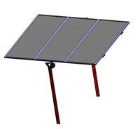
solar tracker
...aterial : -arduino uno -2 step motor with driver -4 ldr sensor -some wires -small photovoltaiic pannel -buzzer -cnc laser machine
turbosquid
$23
E3D -HTC Vive Tracker
...model e3d -htc vive tracker for download as max, obj, and c4d on turbosquid: 3d models for games, architecture, videos. (1190728)
3d_export
$7

sci-fi injector or tracker
... can be tracker, use as you want. pbr 4k contain: blend (includes high poly)/ dae / fbx / obj / stl / glowing injector + box
3d_export
$10

Motion Tracker Aliens
...er out moving objects from stationary background and then displayed them on the monitor as a series of contours of probable loci.
3d_export
$5
single axis solar tracker stand
...single axis solar tracker stand
3dexport
3d_export
$60
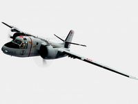
grumman s-2 f tracker
...ining in service with other air arms into the 21st century. argentina and brazil are the last countries to still use the tracker.
3d_export
$19

Chevrolet tracker 2021
...pport ticket and request for that. we can convert 3d models to: .stl, .c4d, .obj, .fbx, .ma/.mb, .lwo/.lws, .3ds, .3dm, .dxf/.dwg
3d_export
$25
emergency power with solar tracker
...cker
3dexport
this is a tool used to distribute electricity during an emergency disaster, it is recommended to use sketchup 2019
Leo
3ddd
$1

Leo
...leo
3ddd
forestier , leo
коллекция люстр leo
3ddd
$1

Zanotta Leo
...zanotta leo
3ddd
zanotta , leo
zanotta leo, барный стул
turbosquid
$79

Leo
... available on turbo squid, the world's leading provider of digital 3d models for visualization, films, television, and games.
turbosquid
$49

Leo
... available on turbo squid, the world's leading provider of digital 3d models for visualization, films, television, and games.
3d_export
$7

leo
...t
leo character model this model consists poly mesh of 95000 polygons, some files like zip , rar , obj , fbx ..etc are attached.
turbosquid
$5

Leo
... available on turbo squid, the world's leading provider of digital 3d models for visualization, films, television, and games.
turbosquid
$5

Leo
... available on turbo squid, the world's leading provider of digital 3d models for visualization, films, television, and games.
3ddd
$1

LEO GIORGETTI
... журнальный , круглый
журнальный столик leo,giorgetti
3ddd
$1

Sato / Leo
... кресло , стул
два офисных стула
производитель: sato
коллекция: leo
3d_export
$5

leo the truck
...leo the truck
3dexport
leo the truck - cartoons for children.<br>[https://www.youtube.com/watch?v=dqxqwvdogfu]
Satellites
archibase_planet
free

Satellite
...satellite space satellite communication satellite
satellite n180314 - 3d model (*.gsm+*.3ds+*.max) for exterior 3d visualization.
turbosquid
$30

Satellite
...osquid
royalty free 3d model satellite for download as blend on turbosquid: 3d models for games, architecture, videos. (1600410)
turbosquid
$75

Satellite
...
royalty free 3d model satellite for download as max and obj on turbosquid: 3d models for games, architecture, videos. (1442437)
turbosquid
$50

Satellite
... available on turbo squid, the world's leading provider of digital 3d models for visualization, films, television, and games.
turbosquid
$50

Satellite
... available on turbo squid, the world's leading provider of digital 3d models for visualization, films, television, and games.
turbosquid
$39

Satellite
... available on turbo squid, the world's leading provider of digital 3d models for visualization, films, television, and games.
turbosquid
$11

Satellite
... available on turbo squid, the world's leading provider of digital 3d models for visualization, films, television, and games.
turbosquid
$10

satellite
... available on turbo squid, the world's leading provider of digital 3d models for visualization, films, television, and games.
turbosquid
$5

Satellite
... available on turbo squid, the world's leading provider of digital 3d models for visualization, films, television, and games.
turbosquid
$3

Satellite
... available on turbo squid, the world's leading provider of digital 3d models for visualization, films, television, and games.