Thingiverse
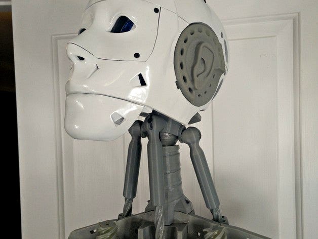
InMoov Articulating Neck Joint ReMix by alansrobotlab
by Thingiverse
Last crawled date: 3 years ago
This is a remix of Bob Houston's outstanding articulated neck mod.
https://www.youtube.com/watch?v=FPV6k8QfDY8
You'll need the following:
(3) 3m x 20mm socket head cap screws
(3) 3m x 12mm machine screws
(3) 3m washers
(7) #6 or #8 3/4" flathead screws or equivalent
(8) #4 1/2" flathead screws or equivalent
Print out every part with the following settings:
100micron layer height
6 perimeters
2mm tops and bottoms
15% infill
3-4mm brim
For ArtNeck_NeckV1 and ArtNeck_NeckUpperV2, I printed those with the same settings but with 250 micron layers. I just couldn't get the settings right to print NeckUpper at 100 microns.
Only these items will require supports:
ArtNeck_ServoHolderV2
ArtNeck_ServoJointUpperV2
Assembly
Drill out NeckUpper Ball Mounts to 2.5mm, then tap 3mm threads. Lightly sand the ball joints and attach to head using #8 screws.
Insert NeckLower into Neck with larger slot facing the back, align then drill, countersink and use a short machine screw to mate together. Make sure you shorten or snip the screw so that it doesn't extend into the neck. Mount new neck subassembly to InMoov with #8 screws. Mount Head NeckUpper to NeckLower. don't jostle.
Sand external surface of ServoPivot Mount point. Drill pivot hole to 2.5mm, then threads to 3mm. Use ServoPivot to drill out the mount holes from the shoulder frame. See photo. Put left servopivot into right facing inward, then drill for correct mount hole locations. countersink. To mount these, you're going to have to temporarily either remove the arm, or remove the rear shoulder panel. Mount using #8 screws.
Sand mating surface for ServoHolder. Drill pivot hold and servo mount holes to 3mm. Test fit into ServoPivot. Can/Should be tight. Mount to ServoPivot using 3mm washer and 12mm machine screw. Make very tight, turns out it doesn't need to pivot at all.
Drill PistonBaseSide to 3-4mm, temporarily mount to servos. Mount servos to ServoHolder using #4 machine screws.
Drill PistonBaseFront to 3-4mm. Remove neck front pistonbase, and temporarily mount to front Neck servo using #4 machine screws.
Enable neck front servo, and set to 90 degrees position. Grease up PistonBaseFront and balljoint. Test fit PistonFront attempting to mate with head level with floor. If all four orientations are either too high or too low, make a note of what change in rotation would be required to make head level (15 degrees, 45 degrees etc). Remove PistonBaseFront, unscrew horn and reset at desired position. Attach PistonBaseFront and try again. Use 20mm socket head cap screw to affix ball joint. Just turn head to side to access/affix front piston socket head cap screw.
Enable neck side servo, and set to 90 degrees position. Grease up PistonBaseSide and balljoint. Test fit PistonSide attempting to mate with head level with floor. If all four orientations are either too high or too low, make a note of what change in rotation would be required to make head level (15 degrees, 45 degrees etc). Remove PistonBaseSide, unscrew horn and reset at desired position. Attach PistonBaseSide and try again. Use 20mm socket head cap screw to affix ball joint.
Whatever control solution you're using, make sure you set sane max/min values for the new neck nod and side actions.
Enjoy! This is a very cool mod. :-)
Updates:
2016-02-28 NeckJointUpper to V3, widened mounting studs, shortened balljoint backplane for a few more degrees of freedom NeckJointLower to V3, thickened balljoint feature, now both slots are same size to match NeckJointUpper Added HK15328 servo horn if you're using that type of servo.
Similar models
thingiverse
free

NEMA 17 Motor Mount by tetralite
... head cap screws of whatever length needed to fasten the mount to the device. the two mounting holes for the part are 28mm apart.
thingiverse
free

Gear Head Adapter by jeremyrichardmann
...e apart the gearhead native mount, the part with the ball-socket joint can be natively screwed into this with a proper 3mm screw.
thingiverse
free

Finger hinge by zerker77
...mounts. the hinge is designed for 3mx16mm bolt. the hinge mount has a hole and countersink, to accept a 3m socket head cap screw.
thingiverse
free

DSLR Tilt by LeoRover
...camera_holder side, then by two small m2 screws on the horn and then using m3x8 screws attach servo to the base. that's it ;)
thingiverse
free

Improved Ball and Socket Joint
... between the lobes, it's more like 90 degrees if you go against them.
the threaded designs can take considerably more weight.
thingiverse
free

Dash Mount with 17mm Ball by RealmKnight
..., etc or i drilled two holes to use m3 screws to attach it to the removable section of my jeep dash. v2 has the holes pre-drilled
grabcad
free

Socket head cap screw M8
...rks which doesn't have smart fasteners. the length can be selected during placement in the assembly and can be adjusted after
thingiverse
free

Bear head parts for 1/12 scale action figure by Shigeru
...bear head parts for 1/12 scale action figure by shigeru
thingiverse
you can use a 3mm ball joint for the neck. have fun!!
grabcad
free

BallJoint
...balljoint
grabcad
balljoint model for kira
updated mates to limit movement of ball
thingiverse
free
![[3in1] Ball & Socket Joint with Screw Hole by DENOVATOR](/t/8858583.jpg)
[3in1] Ball & Socket Joint with Screw Hole by DENOVATOR
...by denovator
thingiverse
ball joint & socket with thread hold. ball snaps tightly into itself. using 'm10x1.5' bolt.
Alansrobotlab
thingiverse
free

HK15328D by alansrobotlab
...ferent than the hitec servos, so you need to take that into account in your designs.
designed using onshapehttp://www.onshape.com
thingiverse
free

InMoov LowArmSideV1 for Square Potentiometer by alansrobotlab
...rse
a quick hack to support the newer hitec servos with the square potentiometer.
the potentiometer fits into the recess snugly.
thingiverse
free

HK15338 by alansrobotlab
....
designed using onshapehttp://www.onshape.com
2015-10-27: quick update, put wire grommet on correct side and reuploaded models.
thingiverse
free

InMoov JawHingeV1 with Opening for Wires by alansrobotlab
...mix of jawhingev1 with an opening for those running wires down through the neck.
i also added some mounting holes to the sides.
thingiverse
free

InMoov 180 degree rotational wrist mod for Anar's Solid CAD Forearm by alansrobotlab
...ar's solid cad forearm by alansrobotlab
thingiverse
180+ degree rotational wrist mod for anar's solid cad inmoov forearm
thingiverse
free

InMoov PivPotentiometerV3 remix for #4 screws, for newer HiTec Rectangular Potentiometer by alansrobotlab
... with larger screw holes a bit further out. makes it alot easier to affix with #4 screws.http://www.thingiverse.com/thing:254664
thingiverse
free

InMoov Faster Rotate/Twist for Bicep by alansrobotlab
...the shoulder pivot next. :-)
i'm not sure how much faster i can make it, as the position of rotgear and rotworm are fixed.
thingiverse
free

InMoov Remix to Allow Full 180 Degree Wrist Rotation by alansrobotlab
... forearm assembly, but edited the cableholder and rotawrist2 models to support my changes.http://www.thingiverse.com/thing:514995
thingiverse
free

InMoov Torso Mods for the XBoxOne Kinect by alansrobotlab
... back.
2016-01-25 sensormount updated, fixed recessed screw holes
2016-01-24 recessed the sensor a bit more. frame parts updated
thingiverse
free

Rostock Max OpenPnP Conversion by alansrobotlab
...easy to adapt to other larger format delta style printers as well.
i'll add in some basic instructions and a parts list soon.
Inmoov
turbosquid
$29

inMOOV by Nina Lieven
...model inmoov by nina lieven for download as max, obj, and fbx on turbosquid: 3d models for games, architecture, videos. (1230519)
thingiverse
free

InMoov KeyChain !!! by Alessandruino
...inmoov keychain !!! by alessandruino
thingiverse
this is an inmoov keychain for you or a fantastic jewel for your inmoov :)
thingiverse
free

Inmoov by joseph02
...inmoov by joseph02
thingiverse
porte clé inmoov, 2 couleurs. imprimé sans raft ni support.
thingiverse
free

inmoov full by ambroise
...inmoov full by ambroise
thingiverse
inmoov full
thingiverse
free

INMOOV EYELID ( PAUPIERES POUR INMOOV ) by heisenberg333
...ov parts .it's made very good .
you can see full tutorial on attached excel file
https://www.youtube.com/watch?v=h_jdau9v5zq
thingiverse
free

Inmoov Legs by kike1978
...inmoov legs by kike1978
thingiverse
inmoov custom legs, not articulated.
thingiverse
free

InMoov Head by Mindylee
...inmoov head by mindylee
thingiverse
inmoov open source hardware
thingiverse
free

inmoov top mouth by mix3rn
...inmoov top mouth by mix3rn
thingiverse
inmoov
thingiverse
free

Stand Inmoov
...the servo drive head.
with this body, you can move your head upright. for movement, you can use the standard inmoov vertical stem
thingiverse
free

back battery inmoov by ambroise
...back battery inmoov by ambroise
thingiverse
back battery inmoov
Articulating
turbosquid
$60

Articulated doll
...e 3d model articulated doll for download as max, obj, and ztl on turbosquid: 3d models for games, architecture, videos. (1277424)
turbosquid
$10
articulated lamp
... available on turbo squid, the world's leading provider of digital 3d models for visualization, films, television, and games.
design_connected
$11
Articulated Industrial Light
...articulated industrial light
designconnected
o. c. white articulated industrial light computer generated 3d model.
cg_studio
$169
Articulated Truck3d model
...cgstudio
.3ds .c4d .lwo .max .obj - articulated truck 3d model, royalty free license available, instant download after purchase.
3d_export
$90

Design Bus Articuled 3D Model
...design bus articuled 3d model
3dexport
design bus articuled
design bus articuled 3d model basshunter 8620 3dexport
turbosquid
$59

Articulated truck 45f
... available on turbo squid, the world's leading provider of digital 3d models for visualization, films, television, and games.
3d_ocean
$130

Caterpillar 725 Articulated Truck
...for close-up renders. scene contain textures, standart scanline, mentalray and vray materials. - high quality polygonal model ...
3d_export
$22

articulated dump truck
...ost popular and not very 3d file formats, as well as textures for shaders.<br>format: 3ds max, obj, fbx, 3ds, lwo, c4d, dae
turbosquid
free

Rigged articulated bus acordion bus for games
...or download as max, max, unitypackage, max, fbx, obj, and 3ds on turbosquid: 3d models for games, architecture, videos. (1599911)
3d_export
$24

dubai bus articulated
...ed check if our models are useful for your project and leave a like if you like this model.<br>thank you for your interest!
Neck
3d_export
$7

Pork neck
...pork neck
3dexport
pork neck
3d_export
free

Gold chain for neck
...gold chain for neck
3dexport
metal gold chain for neck
3d_export
$6

neck brush
...neck brush
3dexport
3d_export
$69

throgs neck bridge
...throgs neck bridge
3dexport
throgs neck bridge. low poly. max 12. fbx. obj. 3ds. one texture.
3d_export
$5

round neck gourd
...round neck gourd
3dexport
turbosquid
$4

Dummy neck for jewelry
...alty free 3d model dummy neck for jewelry for download as 3ds on turbosquid: 3d models for games, architecture, videos. (1603064)
3d_export
$90

Neck nerves 3D Model
...neck nerves 3d model
3dexport
anatomy
neck nerves 3d model evarobin3d 15676 3dexport
turbosquid
$150

double neck guitar
... available on turbo squid, the world's leading provider of digital 3d models for visualization, films, television, and games.
turbosquid
$150

Double Neck Guitar
... available on turbo squid, the world's leading provider of digital 3d models for visualization, films, television, and games.
turbosquid
$40

Square Neck Dress
... available on turbo squid, the world's leading provider of digital 3d models for visualization, films, television, and games.
Joint
turbosquid
$5

Joint
...turbosquid
royalty free 3d model joint for download as blend on turbosquid: 3d models for games, architecture, videos. (1179882)
3d_export
$5
joint handle
...joint handle
3dexport
joint handle
3d_export
$5
knuckle joint
...knuckle joint
3dexport
this is a 3d model of knuckle joint
3d_export
$5
Knuckle Joint
...knuckle joint
3dexport
industry use knuckle joint
3ddd
$1
PENTA Joint
...penta joint
3ddd
penta
http://www.lampcommerce.com/en/catalogue/brands/penta-light/joint-floor-lamp
turbosquid
$49
Joint | Project
...squid
royalty free 3d model joint | project for download as on turbosquid: 3d models for games, architecture, videos. (1297983)
turbosquid
$10

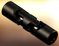
universal joint
...squid
royalty free 3d model univresal joint for download as on turbosquid: 3d models for games, architecture, videos. (1309400)
turbosquid
$15

Joint Ashtray
...squid
royalty free 3d model joint ashtray for download as ma on turbosquid: 3d models for games, architecture, videos. (1199702)
turbosquid
$5

Unrolled joint
...e 3d model unrolled joint for download as blend, obj, and stl on turbosquid: 3d models for games, architecture, videos. (1577889)
3d_export
$5
Cardan Joint 3D Model
...cardan joint 3d model
3dexport
cardan joint
cardan joint 3d model fau 71171 3dexport
Remix
turbosquid
$5
MODA Collection Remix Chair
... available on turbo squid, the world's leading provider of digital 3d models for visualization, films, television, and games.
3d_export
$12
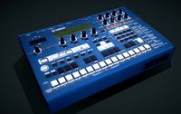
remix yamaha rm1x
...remix yamaha rm1x
3dexport
geometry triangles 15.2k vertices 7.6k pbr no textures 1 materials 1 uv layers yes
3d_ocean
$5
Vray fabric Kvadrat remix green - tileable
...th vray and 3dsmax. high-resolution texture images (2000×2000 px) file included: shader vray 2.40 texture image 3ds max 2011 file
turbosquid
$20

Gerrit Rietveld 1938 Zig Zag Chair Remix
... available on turbo squid, the world's leading provider of digital 3d models for visualization, films, television, and games.
3d_export
$10

multicolored remix parametric table furniture
... fbx, obj, mtl, archive with textures. the model has no glitches. render and materials - vray . without using plugins. good use!
3ddd
$1
Barovier&Toso / Manhattan Remix 7192
... 004293-142405
в коллекции есть люстры 7, 9, 12 рожковые. диаметр соответственный 1000, 1250, 1500 мм.
3ddd
$1
Muuto fiber chair
...grey/grey, dusty green/dusty green, nature/oak, natural white/oak upholstery options remix 183/black, remix 133/grey, remix 643/dusty red leather options black...
3ddd
$1
Barovier&Toso 7190-7195
...7190-7195 3ddd barovier&toso потолочнай люстра фабрики barovier&toso;, коллекция manhattan remix артикул 7190-7195. размеры в inches: 39"...
3d_export
$5
3D Locking Handle Weatherproof Storage Box Container
...handle weatherproof storage box container 3dexport new, improved and remixd! no screws required. print-in-place. weatherproof. parametric. 2 parts. easy...
cg_studio
$49

HTC One Mini 2 Amber Gold3d model
...cell phone mobile cellular super lcd touchscreen touch screen remix amber gold .max .obj .mb .lwo .fbx .c4d .3ds...