Thingiverse
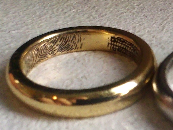
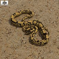
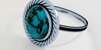
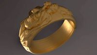
Image to Textured Anulus (Ring) Python Tool by M_G
by Thingiverse
Last crawled date: 2 years, 12 months ago
originally this was a script to convert images to height maps as polyhedrons suitable for use in openscad...now it has become a tool for making height map textured ring shapes
ToDo
add control for fading edges of image
v0-13
modifications based on prototype from i.materialise
Ring .stl internal diameter seemed to be 6 or 16.5mm, but size is entered correctly as 6.5 or 16.9mm which is correct
GENERATING A NON-TEXTURED RING GIVES CORRECT DIMENSIONS however adding an embossed texture to the inside adds material
Fixed!!!
in... if texture:
if texture_inside_not_outside:
print "texture inside not outside"
if texture_engraved_not_raised:
#changes made here to fix texture size issue
NOW vertex_list.append([row*height_scaling,column,texture_depth - (pix[row,column]*depth_scaling) ])
WAS vertex_list.append([row*height_scaling,column, - (pix[row,column] *depth_scaling) ])
sizes/etc changed for 2nd prototype/production version
texture_depth=0.2 #to match prototype which turned out well, default was 0.5
ring_width=4.4 #to match engagement ring, default was 4
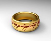
inputImage = 'slightlycleanedbetter_text.png' to include engraving text
texture_height_ring_circum_ratio=1#changed from 0.6 to take account of longer texture image featuring text
doming looks good now with adjusted shape
v0-12
add control for how much of ring is covered in pattern
added texture_scale ability
possibly this introduces shadows at the edges... perhaps have option to trim 1 pixel from
each edge before using for texture to prevent this?
identified possible bug with texture direction when only using partial coverage
identified possible bug where back vertical edges have gaps...possibly due to ctrl+h replacing of
width and height previously...blergh!
reduced the number of holes and bad edges but still not perfect... this requires further
attention as at the moment it generates bad .STLs!!!
fixed!!!
v0-11
Now can directly make the entire ring!
ability to invert/flip/rotate image
add control over emboss/engrave
fix jumbled up width and height
removed openscad output options to functions
removed make_square section to function
add control for placing image on inner/outer surface
control the shapes of inner/outer surface so can directly create final ring
curvature direction and amount on inner and outer surface
add 2 separate ellispe radii for each surface implementing simple control over curving in
second direction
fixed some bugs where curved surfaces shape and change in height was miscalculated
Only tested on combinations of flat and convex...possibly bugs in concave surfaces???
v0-10
implement curving in second direction
cleanup code
v0-9
Moved items to main
fixed calculation of ring width
added ability to connect ends together so you can get a complete ring
add option for direct output in ascii .stl format (from https://en.wikipedia.org/wiki/STL_
%28file_format%29 )
An STL file describes a raw unstructured triangulated surface by the unit normal and vertices
(ordered by the right-hand rule) of the triangles using a three-dimensional Cartesian coordinate
system. STL coordinates must be positive numbers, there is no scale information, and the units are
arbitrary.
An ASCII STL file begins with the line:
Line 1
solid name
where name is an optional string (though if name is omitted there must still be a space after solid). The file continues with any number of triangles, each represented as follows:
Line 2 to n-1
facet normal ni nj nk
In both ASCII and binary versions of STL, the facet normal should be a unit vector
pointing outwards from the solid object. In most software this may be set to (0,0,0) and the software will automatically calculate a normal based on the order of the triangle vertices using
the 'right-hand rule'
outer loop
vertex v1x v1y v1z
vertex v2x v2y v2z
vertex v3x v3y v3z
endloop
endfacet
where each n or v is a floating point number in sign-mantissa 'e'-sign-exponent format, e.g.,
"-2.648000e-002". The file concludes with:
Line n
endsolid name
v0-8
3d graph of vertex points with ID numbers
v0-7
simple hack around failure with non-square images by adding blank pixels to edges to make it square! This works but leaves flat parts at the edges uses the maxima from im.extrema() to scale the texture heights uses user input to select width of output polygon via x position of vertex points
began attempt to join ends together
v0-6
vertex array is now curved in 1 dimension
v0-5
all data is saved to arrays rather than written immediately to file this will allow for easier editing
v0-4
moved all polygon and triangle surface generation (textured top, flat bottom & sides) into single block
swapped order of side 4 in attempt to fix winding order
This can now generate a valid 3d polyhedron... but openscad has trouble with non-square input textures (not sure why)
v0-3 2013-01-09
Now able to generate all surfaces...still need to integrate this all into one method (removing special values) so they can form one object!
Cleaned up section that generates upper surface so it is more like that used to generate subsequent surfaces (easier to read and integrate)
v0-2 2013-01-09
converted to use load() (for better speed) based on http://stackoverflow.com/questions/11064786/get-pixels-rgb-using-pil
Add option to output simple cube (set op_format=1) or ployhedron (triangles) based maps (set op_format=0)
added base_thickness
added ability to direct output to file (greatly speeds up operation)
Fixed output of base polygon so it appears at the end!
Having difficulties generatign the edges and sides
v0-1 2013-01-08
simple script to open a simple diagonal greysale_10x10_diagonal image in multiple formats and extract pixel data for manipulation
code initially taken from here http://stackoverflow.com/questions/14111705/python-displaying-a-grayscale-image
It will calculate the "elevation" for each pixel using the average RGB value as a height, kinda like a height/bump-map
an attempt to create an openscad compatible ployhedron object containing a list of vertices and triangles
Note:
Current output can be viewed in Openscad but cannot be rendered and output unless input is square!!!
ToDo
add control for fading edges of image
v0-13
modifications based on prototype from i.materialise
Ring .stl internal diameter seemed to be 6 or 16.5mm, but size is entered correctly as 6.5 or 16.9mm which is correct
GENERATING A NON-TEXTURED RING GIVES CORRECT DIMENSIONS however adding an embossed texture to the inside adds material
Fixed!!!
in... if texture:
if texture_inside_not_outside:
print "texture inside not outside"
if texture_engraved_not_raised:
#changes made here to fix texture size issue
NOW vertex_list.append([row*height_scaling,column,texture_depth - (pix[row,column]*depth_scaling) ])
WAS vertex_list.append([row*height_scaling,column, - (pix[row,column] *depth_scaling) ])
sizes/etc changed for 2nd prototype/production version
texture_depth=0.2 #to match prototype which turned out well, default was 0.5
ring_width=4.4 #to match engagement ring, default was 4
inputImage = 'slightlycleanedbetter_text.png' to include engraving text
texture_height_ring_circum_ratio=1#changed from 0.6 to take account of longer texture image featuring text
doming looks good now with adjusted shape
v0-12
add control for how much of ring is covered in pattern
added texture_scale ability
possibly this introduces shadows at the edges... perhaps have option to trim 1 pixel from
each edge before using for texture to prevent this?
identified possible bug with texture direction when only using partial coverage
identified possible bug where back vertical edges have gaps...possibly due to ctrl+h replacing of
width and height previously...blergh!
reduced the number of holes and bad edges but still not perfect... this requires further
attention as at the moment it generates bad .STLs!!!
fixed!!!
v0-11
Now can directly make the entire ring!
ability to invert/flip/rotate image
add control over emboss/engrave
fix jumbled up width and height
removed openscad output options to functions
removed make_square section to function
add control for placing image on inner/outer surface
control the shapes of inner/outer surface so can directly create final ring
curvature direction and amount on inner and outer surface
add 2 separate ellispe radii for each surface implementing simple control over curving in
second direction
fixed some bugs where curved surfaces shape and change in height was miscalculated
Only tested on combinations of flat and convex...possibly bugs in concave surfaces???
v0-10
implement curving in second direction
cleanup code
v0-9
Moved items to main
fixed calculation of ring width
added ability to connect ends together so you can get a complete ring
add option for direct output in ascii .stl format (from https://en.wikipedia.org/wiki/STL_
%28file_format%29 )
An STL file describes a raw unstructured triangulated surface by the unit normal and vertices
(ordered by the right-hand rule) of the triangles using a three-dimensional Cartesian coordinate
system. STL coordinates must be positive numbers, there is no scale information, and the units are
arbitrary.
An ASCII STL file begins with the line:
Line 1
solid name
where name is an optional string (though if name is omitted there must still be a space after solid). The file continues with any number of triangles, each represented as follows:
Line 2 to n-1
facet normal ni nj nk
In both ASCII and binary versions of STL, the facet normal should be a unit vector
pointing outwards from the solid object. In most software this may be set to (0,0,0) and the software will automatically calculate a normal based on the order of the triangle vertices using
the 'right-hand rule'
outer loop
vertex v1x v1y v1z
vertex v2x v2y v2z
vertex v3x v3y v3z
endloop
endfacet
where each n or v is a floating point number in sign-mantissa 'e'-sign-exponent format, e.g.,
"-2.648000e-002". The file concludes with:
Line n
endsolid name
v0-8
3d graph of vertex points with ID numbers
v0-7
simple hack around failure with non-square images by adding blank pixels to edges to make it square! This works but leaves flat parts at the edges uses the maxima from im.extrema() to scale the texture heights uses user input to select width of output polygon via x position of vertex points
began attempt to join ends together
v0-6
vertex array is now curved in 1 dimension
v0-5
all data is saved to arrays rather than written immediately to file this will allow for easier editing
v0-4
moved all polygon and triangle surface generation (textured top, flat bottom & sides) into single block
swapped order of side 4 in attempt to fix winding order
This can now generate a valid 3d polyhedron... but openscad has trouble with non-square input textures (not sure why)
v0-3 2013-01-09
Now able to generate all surfaces...still need to integrate this all into one method (removing special values) so they can form one object!
Cleaned up section that generates upper surface so it is more like that used to generate subsequent surfaces (easier to read and integrate)
v0-2 2013-01-09
converted to use load() (for better speed) based on http://stackoverflow.com/questions/11064786/get-pixels-rgb-using-pil
Add option to output simple cube (set op_format=1) or ployhedron (triangles) based maps (set op_format=0)
added base_thickness
added ability to direct output to file (greatly speeds up operation)
Fixed output of base polygon so it appears at the end!
Having difficulties generatign the edges and sides
v0-1 2013-01-08
simple script to open a simple diagonal greysale_10x10_diagonal image in multiple formats and extract pixel data for manipulation
code initially taken from here http://stackoverflow.com/questions/14111705/python-displaying-a-grayscale-image
It will calculate the "elevation" for each pixel using the average RGB value as a height, kinda like a height/bump-map
an attempt to create an openscad compatible ployhedron object containing a list of vertices and triangles
Note:
Current output can be viewed in Openscad but cannot be rendered and output unless input is square!!!
Similar models
thingiverse
free

Parametric window sill end caps by maximrus
...y to select the number of parts: of left, right or both parts.
28.08.2018 - the ability to adjust the height of the frame added.
thingiverse
free

Sprocket Generator V2.1 - OpenSCAD
...
grouping of and helpful descriptions for options
fixes
fixed always having one hole added, even if the quantity was set to zero
thingiverse
free

Honeycomb Pattern Generator by XYZAidan
...e number of hexagons in a row
spacing - the thickness of the lines of the pattern
height - height of the pattern when extruded up
thingiverse
free

Stackable Parts Bin (Parametric) by lizard00
...g for invalid parameters.
the files include a few bug fixes from the initial posting that should now make the parts stack better.
thingiverse
free

Yet Another Tool/Pen Desk Organizer (parametric) by DonJuanito
......
i hope it will be useful...
edit 12/5/2015 : i uploaded v1.1 with a bug correction: the height seletion now works :( sorry...
thingiverse
free

SVG to OpenSCAD Bezier - InkScape extension by gaellafond
... and anton moiseev (sadr0b0t)
[2018-06-29] fixed bug with the "translate" function, when document is not in pixel unit.
thingiverse
free

universal tube creator with holder by Winne
...x many bugs and add a holder
2015-01-13 add an auto position holder
2015-01-18 fixed holder bug
2015-02-26 wall thiness bug fixed
thingiverse
free

Shed door slider by mmariage
...
got a shed from a neighbour with a broken door slider. now its fixed.
added the openscad too just incase you wanted to add to it
thingiverse
free

Gyroscopic Relaxing Keyring Generator for 3D printing by ZAV
...cad development snapshots 2016.10.04
за основу модели была взята идея gianfranco crevani http://www.thingiverse.com/thing:1307100
thingiverse
free

Note-Generator by Synchron
...wiki/file:music_rests.svg
for generating the openscad-code from svg i used:https://github.com/martymcguire/inkscape-openscad-poly
Anulus
thingiverse
free

15mm pipe clip for 18B20 and other TO92 devices by simon0362
...and to be filled with e.g. epoxy to seal. anulus at the cable end acts as a basic cable...
thingiverse
free

P-clip for 18b20 or other TO92 devices by simon0362
...the open end of the tube has a small anulus to act as a strain relief if epoxy is...
cg_trader
$30

anulus | 3D
...anulus | 3d
cg trader
testere kesim
cg_trader
$25

fashion anulus
...l jewellery diamond ring wedding gem fashion ring necklace engagem apparel bracelate brilliant sterling scanned 3d models various
cg_trader
$25

fashion anulus
...ond ring wedding gem fashion ring necklace engagem apparel bracelate brilliant sterling white gold ring scanned 3d models various
Python
turbosquid
$12
Colt Python
...osquid
royalty free 3d model colt python for download as fbx on turbosquid: 3d models for games, architecture, videos. (1189141)
turbosquid
$15
Colt Python
...y free 3d model colt python for download as obj, fbx, and dae on turbosquid: 3d models for games, architecture, videos. (1494289)
turbosquid
$40
Colt Python
... available on turbo squid, the world's leading provider of digital 3d models for visualization, films, television, and games.
turbosquid
free

Python Battlecruiser
... available on turbo squid, the world's leading provider of digital 3d models for visualization, films, television, and games.
turbosquid
free
Colt Python
... available on turbo squid, the world's leading provider of digital 3d models for visualization, films, television, and games.
3d_export
$65
Python 3D Model
...odel
3dexport
snake viper mamba adder reptiles cold blood boa python constrictor animals
python 3d model grafikdon 17363 3dexport
turbosquid
$40
colt python .357
... available on turbo squid, the world's leading provider of digital 3d models for visualization, films, television, and games.
3d_export
$20
Python Snake Cake
...amp;_sid=c911d3a32&_ss=r<br>textures 4096*4096px pbr photoscan-based materials base color, normal, roughness, specular)
humster3d
$50

3D model of Colt Python
...
buy a detailed 3d model of colt python in various file formats. all our 3d models were created maximally close to the original.
humster3d
$40
3D model of Common Python
...buy a detailed 3d model of common python in various file formats. all our 3d models were created maximally close to the original.
G
3ddd
free
G. Moscatelli
...алка
вешалка 25 / 26 / 27коллекция: belle heleneбренд: g. moscatelliстрана: италияразмеры: высота - 190 / 195; диаметр - 50 / 60.
3ddd
$1
G Plan Vintage
...g plan vintage
3ddd
винтаж , g plan
g plan vintage armchair
turbosquid
free
G protein
...otein
turbosquid
free 3d model g protein for download as c4d on turbosquid: 3d models for games, architecture, videos. (1309660)
turbosquid
$14

Fence G
...turbosquid
royalty free 3d model fence g for download as fbx on turbosquid: 3d models for games, architecture, videos. (1310122)
turbosquid
$7

G for Gun
...rbosquid
royalty free 3d model g for gun for download as max on turbosquid: 3d models for games, architecture, videos. (1685215)
turbosquid
$5

Letter G
...urbosquid
royalty free 3d model letter g for download as max on turbosquid: 3d models for games, architecture, videos. (1408463)
turbosquid
$5

Letter g
...urbosquid
royalty free 3d model letter g for download as max on turbosquid: 3d models for games, architecture, videos. (1408408)
turbosquid
$5

G Ring
...
turbosquid
royalty free 3d model g ring for download as stl on turbosquid: 3d models for games, architecture, videos. (1285079)
3ddd
$1

Infiniti / G-Chair
...infiniti / g-chair
3ddd
infiniti
www.infinitidesign.it/ita/g-chair.php
3ddd
$1
кресло G-68
...кресло g-68
3ddd
кресло
кресло руководителя g-68
Tool
turbosquid
$21
Tool box with tools
... available on turbo squid, the world's leading provider of digital 3d models for visualization, films, television, and games.
archibase_planet
free
Tools
...tools
archibase planet
tools instruments implements
tools n070114 - 3d model (*.gsm+*.3ds+*.max) for interior 3d visualization.
3d_ocean
$12
Tools
...tools
3docean
hammer metal old screw tools wrench
maya
turbosquid
$6

Tool Cart / Tool Box
...
royalty free 3d model tool cart / tool box for download as on turbosquid: 3d models for games, architecture, videos. (1241859)
3d_ocean
$15
crimp tool
... tool copper cutter crimp crimp tool electrical electrical tools press tools pressing tool tools wire cutter
created in maya 2013
3d_ocean
$5
Tools
...tools
3docean
3d models paint tools work
3d,models,works,paint,art,create,working,
3d_export
free
tools
...tools
3dexport
coldsteel
turbosquid
$15
Tools
...turbosquid
royalty free 3d model tools for download as blend on turbosquid: 3d models for games, architecture, videos. (1331352)
3ddd
$1
bar tool
...bar tool
3ddd
барный
bar tool
turbosquid
$35
tools
... available on turbo squid, the world's leading provider of digital 3d models for visualization, films, television, and games.
M
turbosquid
$20
Stage M&M
... available on turbo squid, the world's leading provider of digital 3d models for visualization, films, television, and games.
3ddd
$1
bag m&m's
...bag m&m's
3ddd
bag m&m's
bag m&m;'s
3d_export
$35
iskander m
...iskander m
3dexport
iskander m 3d model
design_connected
$7
barstool m
...barstool m
designconnected
barstool m computer generated 3d model.
3ddd
free
CACTUS M
...cactus m
3ddd
cactus , lzf
настольный светильник cactus m
производитель lzf
design_connected
$13
Anfora M
...anfora m
designconnected
lzf anfora m computer generated 3d model. designed by herranz, miguel.
3ddd
$1
зеркало M Gastone
...зеркало m gastone
3ddd
зеркало m gastone
зеркало m gastone
design_connected
$16
Dogon M
...dogon m
designconnected
emmemobili dogon m chairs computer generated 3d model. designed by ferruccio laviani.
design_connected
$9
Sunlight M
...sunlight m
designconnected
bonacina pierantonio sunlight m computer generated 3d model. designed by bizzozzero, franco.
3ddd
$1
Karman / Norma-M
...arman , norma-m
http://www.karmanitalia.it/en/prodotto/norma-m/norma-m-ap640n/
Image
turbosquid
$5

Image Cube
...ty free 3d model image cube for download as obj, stl, and dae on turbosquid: 3d models for games, architecture, videos. (1659119)
turbosquid
$6

Castle image
... available on turbo squid, the world's leading provider of digital 3d models for visualization, films, television, and games.
turbosquid
free

Tribal Image
... available on turbo squid, the world's leading provider of digital 3d models for visualization, films, television, and games.
turbosquid
free

stereoscopic image
... available on turbo squid, the world's leading provider of digital 3d models for visualization, films, television, and games.
3ddd
free

Bridgeman Images “Flowers”
...idgeman images “flowers”
3ddd
bridgeman images , цветы
сборник работ от bridgeman images
3ddd
$1

Image 3
... низким положением.
внешние размеры - 220,8 см x 104,0 смhttp://www.linet.com/health-care/beds/universal-beds/image-3/
3ddd
free

ASTRO IMAGE 0410
...astro image 0410
3ddd
astro
image interior wall-light. mirror finish, white opal glass diffuser. suitable for bathroom.
turbosquid
$9

Stone lecalo image
...
royalty free 3d model stone lecalo image for download as max on turbosquid: 3d models for games, architecture, videos. (1481251)
turbosquid
$6

Image Plates Collection
...alty free 3d model image plates collection for download as ma on turbosquid: 3d models for games, architecture, videos. (1622819)
turbosquid
$4

Simple image block
...oyalty free 3d model simple image block for download as blend on turbosquid: 3d models for games, architecture, videos. (1682450)
Ring
3d_export
$5
ring
...ring
3dexport
ring
3d_export
free

ring
...ring
3dexport
ring
3d_export
free

ring
...ring
3dexport
ring
3d_export
free

ring
...ring
3dexport
ring
3d_export
$10
ring
...ring
3dexport
lord of the rings
3d_export
$5
ring
...ring
3dexport
golden ring
3d_export
free
ring
...ring
3dexport
cherub ring
3d_export
$10
ring
...ring
3dexport
3d ring model
3d_export
$5
ring
...ring
3dexport
ring 3d model
3d_export
$5

ring
...ring
3dexport
ring top black...
Textured
3d_ocean
$5

Textured Plaster Seamless Texture
...fect for gaming and animation. created from photographs. texture, bump, normal jpg maps are all included in this download! enjoy!
3d_ocean
$6

Texture Bundle
...s i have and will make these six textures were made in photoshop and may requier photoshop or programs like photoshop to edit ...
3d_ocean
$4

Tile Textures
...le dark easy green grungy mosaic mosaic textures mosaica pattern texture tileable tiled tiles
8 colored tileable mosaic textures.
3d_ocean
$5

Textured Ceiling Plaster Seamless Texture
...tion. created from photographs. texture, displacement, normal jpg maps are all included in this download! displacement map can...
3ddd
$1

texture wood
...texture wood
3ddd
texture wood
3ddd
free

Wood texture
...wood texture
3ddd
wood texture
3d_ocean
$3

Wool texture
...wool texture
3docean
seamless wool texture
3ddd
$1

classic texture
...classic texture
3ddd
high resolution texture
3ddd
$1

Concrete texture.
...concrete texture.
3ddd
бетон
concrete texture.
3d_ocean
$12

Granite texture
... (each in separate png file, 2400×1500 px) and one large tileable texture with bump/displacement and specular map (6000×6000 p...