Thingiverse

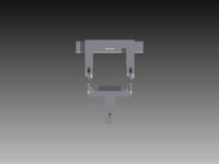
Hotas Cougar Gimbal Redesign by hberg32
by Thingiverse
Last crawled date: 3 years, 3 months ago
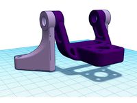
This is a replacement for the notorious gimbal mechanism used in the Thrustmaster Hotas Cougar. This design is influenced by the work of olukelo and debolestis. There are a few key goals with this design:
Retain the factory post (the piece that the grip's M25 ring screws onto)
Allow for either a spring-centered or cam-centered assembly
Required Hardware
(2) Littlefuse 55300 hall sensors
(2) 5x5x3mm neodymium magnets
(2) MR106 bearings
(2) 688ZZ bearings
(3) 40mm M3 bolts
(2) 30mm M3 bolts
(6) 25mm M3 bolts
(4) 20mm M3 bolts
(2) 15mm M5 bolts
(4) 10mm M2 bolts
(4) 25mm M4 flat head bolts
4-8 1 inch or 25mm extension springs
(4) M4 washers
Springs
I found that the Cougar's grip is so heavy that I needed fairly stiff springs just to keep it from flopping over. The spring force is very important to pay attention to. I ended up going with Grainger 1NBH6 springs which have a spring force of 18.94 lbs/inch. 4 of these are enough to hold the stick upright and will give a fairly loose feel. Doubling these to 8 springs gives a pretty stiff feel. Using 4 1NBH6 and 4 1NBH4 (which has a spring force of 10.6 lbs/inch) gives a balanced feel.
Cams
The dual cam mechanism created by olukelo is a fantastic alternative to springs and I have included mounting holes in this design so that they can be used HOWEVER, they are too tall for the Cougar's base. I'm exploring the idea of a printable base height extension but would welcome any ideas on how to design shorter versions of these cams.
Printing
Use plenty of infill for strength. Rotate parts so that surfaces vital for concentricity (such as bearing holders and pivot block posts) face upward. The only part that is tricky to print is the stick surround. Split this part in half when printing and use high detail. The stick surround needs to grip the metal factory post tightly and fit precisely between the bearing planes to avoid any stick wobbling or center play. This part is designed with 0 gaps for mechanical tolerance so sanding will almost certainly be required where the ball bearing grips the stick surround.
Assembly
Be careful not to overtighten screws to avoid stripping the holes. I have not modeled any nut traps in the parts because I think they will weaken them so all bolts here just screw into the plastic. I believe the parts are thick enough that the bolts will not loosen but time will tell.
Completely disassemble the old gimbal mechanism and hurl both it and the potentiometers it came with into the nearest convenient dumpster, lake, or bonfire. Carefully tease off the JST connector from the wires coming out of the metal post and remove the mini-din connector. This will ensure you don't nick the wires when running a reinforcement bolt later.
Screw M5 bolts through the pivot blocks to provide reinforcement
Screw M3 bolts through the the smaller post on the pivot blocks. This is to provide reinforcement so the spring forces don't break off the post. Run the screw from the inside (same direction as the M5 bolt), that way when installing the springs you don't have to get them over the bolt head.
Screw M3 bolts into the cam follower/spring mount posts in the stick surround. These are also for reinforcement and should be screwed from the inside out. There are two posts on each stick surround piece, the cam follower/spring mount is the one that does not have a flat circle around it.
Sand the mating surfaces of the stick surround pieces to ensure they grip the stick tightly or else the stick will have a little wobble. It is not necessary to sand the inside curve surfaces. The flat surface around the pivot posts will be gripped by the bearings. It is important to file these a little bit to ensure that the assembled stick surround measures exactly 28.5mm wide at these flat spots. Over sanding will lead to a bit of stick wobble which can be corrected by adding an M3 shim. Under sanding will lead to a poor fit of the bearing planes. If you don't have calipers use the pivot blocks as a measuring guide. The assembled stick surround should be the same width at the flat spots as the pivot blocks.
Press 688zz bearings into the brackets. Tap these down to make sure they go all the way in. Press MR106 bearings into the bearing planes.
Put the factory metal post into the joystick housing first, then place the stick surround pieces onto it and secure them with 4 M2 bolts. If you assemble the whole gimbal outside of the housing and try to put it in afterward you'll find that the metal post doesn't fit through the hole in the housing. Not that I made that mistake a few dozen times. :)
Place the bearing planes on the stick surround with the bearings facing inward. The pivot posts should go through the bearings. Run a single M3 bolt through the pivot posts to secure the planes and to provide reinforcement.
Mount the pivot blocks using M3 bolts. Use longer bolts in the upper holes and leave them sticking out a bit - the springs will go over these bolts.
Put a magnet in the notch in one of the pivot posts and attach one of the Littelfuse hall sensors over it. Both bearing planes have holes for the sensor but it should be mounted on the one facing the rear of the controller. If you put it on the front plane then left/right stick movement will be backwards.
Attach the other Littelfuse sensor to the left-hand bracket. If you find that forward/backward stick movement is reversed then move the sensor to the other bracket.
Place a magnet in the notch in the pivot block post.
Place the brackets on the pivot blocks.
Bolt the gimbal assembly into the joystick housing.
Run M3 bolts into the brackets (direction doesn't matter).
Install the springs.
The circuit board is secured by 4 screws but we actually need to shim it out a little - otherwise the bolts for the springs will come into contact with the board at full stick deflection. Before putting in the circuit board, run in the 2 screws nearest the center of the joystick assembly, then put in the circuit board and secure it gently with the other two screws. The screw heads provide the perfect amount of shimming (about 5-7mm).
Shimming the circuit board will bring it into contact with the metal baseplate and cause a short circuit so the baseplate needs to be shimmed a little as well. Tape M4 washers over the holes on the inside of the baseplate before putting it back on.
Calibrate the joystick before using it via the Cougar Control Panel app. The Littelfuse sensors return a smaller range of analog values than the original pots did so without calibration you won't be able to get into all four corner.
Good luck and don't let the magic smoke out.
Influences
https://www.thingiverse.com/thing:2496028https://www.shapeways.com/shops/debolestis
Similar models
thingiverse
free

Joystick gimbal by olukelo
...al by olukelo
thingiverse
joystick gimbal with separate axis loading with curved cams. smooth and precise. for magnetic sensors.
thingiverse
free
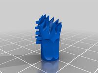
Spikey Gimbal Stick M3 by xgoodvibesx
...etrical design and spikes. this is my favourite so far. tap with an m3 screw beforehand or you'll screw your gimbal post off.
thingiverse
free

Simple Handheld ActionCam/ Camera Gimbal Grip 2D or 3D Hand Held by PHolzwarth
...
optionally a "rocker gimbal joystick"
see the photos for these parts, and the howto.pdf on how to assemble everything.
thingiverse
free
Joystick with halleffect sensors pro micro by FeLep_de
...or rubberbands
microswitches
potentiometer
endstopswitch
wires
2 linear hall effect sensors
youtube: https://youtu.be/pyabw7raivi
thingiverse
free
WIP flexure joystick gimbal by Dmytry
...e cut out fits my office chair's wheel, i put it under the wheel to hold the stick down and also keep the chair from rolling.
thingiverse
free

Filament sensor by denmx
...t in 2 copyes.
connect wire to spring and insert it inside. put sphere at spring and connect two part of this gadget by m3 bolts
thingiverse
free

Camera holder for C-Go1 and gimbal Walkera G2d or G-2d by theletech
...verse
stick the sensor of gimbal behind the trench behind by double sided tape (2 side tape)
use 2mmx15mm screws to hold the cam
thingiverse
free
3-Axis Brushless Gimbal Joystick Plate (offset) by Simonwlchan
...#39;ve left a gap for the connector and built in 4 securing rings that support m3 screws (6mm would suffice - and i only used 2).
thingiverse
free
Nimble Gimbal For 2020 Delta Frame by quadcells
... on the motor bracket button head first. do the same for the other bearing assembly.
please see the provided photos for assembly.
thingiverse
free

joystick + 4 switches remote by CL0
... less than m3. if you don't assemble them like a madman, i found this solution is perfect for light object like the joystick.
Hberg32
thingiverse
free

Cape Hatteras Lighthouse Masking Guide by hberg32
...use tower and tie on some string or fishing line to help align the masking tape. each string should wrap around the tower twice.
thingiverse
free

Single cylinder steam engine by hberg32
...ctures are helpful.): http://modell-dampf-forum.info/wbb4/index.php?thread/6768-stehende-einzylinder-dampfmaschine/&pageno=4
Hotas
3d_export
$60

mikoyan gurevich mig-29 k fulcrum
...radar and several new cockpit displays; the adoption of hotas (hands-on-throttle-and-stick) controls; the integration of rvv-ae (also known as...
3d_export
$60

Silent Bat sixth generation stealth fighter jet
...cockpit is fully digital, it includes several parts : hotas (throttle and stick), wide screen, ejection seat, pedals ...<br>designed...
3d_export
$80

Arrow sixth generation stealth fighter jet
...fully digital, so no mechanical control, except for the hotas (throttle and stick), with wide broken screen, ejection seat,...
3d_export
$150
silent falcon the next generation stealth fighter jet
...fully screen, so no physical control, exept for the hotas (throttle and stick). the main screen is big and...
thingiverse
free
Thrustmaster T16000m hotas baseplates by pernahajder
...thrustmaster t16000m hotas baseplates by pernahajder
thingiverse
baseplates for thrustmaster t16000m hotas
thingiverse
free

HOTA D6 Pro case by WHH
...hota d6 pro case by whh
thingiverse
hota d6 pro case
thingiverse
free

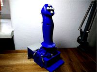
DxRacer HOTAS mount by BayneSolo
...or my hotas on my dxracer chair.
provides a fairly sturdy platform with a little bit of play on the x axis but unoticable in use.
thingiverse
free

Hotas Support / Mount by Stopin
...d seems to be enought.
from my experience, no support is needed, you only need to properly set the print position for each thing.
thingiverse
free

Thrustmaster HOTAS X brackets
...thrustmaster hotas x brackets
thingiverse
please remove the rubbers on joystick bottom.
thingiverse
free

Hotas Warthog Wheelstand Pro Mount
...mount for connecting the thrustmaster hotas warthog stick with the wheelstand pro deluxe v2. you don't need any extra screws.
Cougar
3d_export
$5

Cougar logo
...cougar logo
3dexport
logo cougar gaming
turbosquid
$20

Pyro Cougar
...3d model pyro cougar for download as blend, fbx, obj, and stl on turbosquid: 3d models for games, architecture, videos. (1551224)
3d_export
$5
gamer table cougar mars
...gamer table cougar mars
3dexport
cougar mars 120 black
3ddd
$1

Ford Cougar 2001
...ford cougar 2001
3ddd
:-)
humster3d
$40

3D model of Cougar
...ter3d
buy a detailed 3d model of cougar in various file formats. all our 3d models were created maximally close to the original.
3d_ocean
$89

Ford Cougar 2002
...y, in real units of measurement, qualitatively and maximally close to the original. model formats: - *.max (3ds max 2008 scanl...
turbosquid
$35
MRAP Cougar one
...ee 3d model mrap cougar one for download as 3ds, fbx, and obj on turbosquid: 3d models for games, architecture, videos. (1596965)
3d_export
$99
Mountain Lion Cougar 3D Model
... lion cougar 3d model
3dexport
mountain lion cougar wild animal cat
mountain lion cougar 3d model progamemodeler 83247 3dexport
turbosquid
free

Beretta 8000 Cougar
... available on turbo squid, the world's leading provider of digital 3d models for visualization, films, television, and games.
3d_export
$5
Spider Man On Cougar Plane
...der man on cougar plane
3dexport
i made a spiderman fan costume, and high detailed model of the cougar plane, hope you enjoy it.
Gimbal
turbosquid
$1
Yuneec Save Stick for Gimbal
... available on turbo squid, the world's leading provider of digital 3d models for visualization, films, television, and games.
3d_export
$20

splashdrone gimbal camera
...nsions. all textures used have been included. thank you for purchasing this model!! click on my username to see more of my models
3d_export
$40
splashdrone 3 plus with gimbal camera
...nsions. all textures used have been included. thank you for purchasing this model!! click on my username to see more of my models
turbosquid
$88
DJI Phantom 2 Quadcopter with gimbal for GoPro HERO4 or 3
... available on turbo squid, the world's leading provider of digital 3d models for visualization, films, television, and games.
3d_export
$5

concentrate box
...concentrate box 3dexport concealer box with handle and gimbal ...
cg_studio
$55
Drone Quadrocopter With Camera Rigged3d model
...fly wing propeller rc video camera sky dron spy gimbal gopro riged aircraft toy .obj .fbx .max .3ds -...
3d_ocean
$29
Drone Quadrocopter With Camera Rigged
...quadrocopter with camera rigged 3docean aircraft camera dron fly gimbal gopro propeller quadrocopter rc riged sky sport spy toy...
3ddd
free
Foucault's Iron Orb
...physicist léon foucault's gyroscope inspired our openwork globe. its double-gimbal frame is built of iron around a nucleus of...
thingiverse
free
Gimbal by tannermichael
...amera and gravity to self level. the gimbal uses .125" axles to pivot on. this gimbal was made using autodesk inventor 2015.
thingiverse
free

2020 Gimbal
...2020 gimbal
thingiverse
2020 gimbal
Redesign
3d_ocean
$45

Hyundai SUV vehicle redesigned
...was redesigned by me. 3d model was created in blender3d.preview images were rendered with realistic plugin yafaray.side view o...
turbosquid
$25

Pagani Huayra Redesign
... available on turbo squid, the world's leading provider of digital 3d models for visualization, films, television, and games.
turbosquid
free

Colt M16 (Redesign)
... available on turbo squid, the world's leading provider of digital 3d models for visualization, films, television, and games.
turbosquid
$30
3D for Pose Scarlet Witch redesign\para Posar redesign Feiticeira Escarlate
... imprimir redesign feiticeira escarlate for download as blend on turbosquid: 3d models for games, architecture, videos. (1700850)
3d_export
$5

Gaz 21 redesign 3D Model
...gaz 21 redesign 3d model
3dexport
gaz 21 volga
gaz 21 redesign 3d model rossergorp 71511 3dexport
turbosquid
$55

Porsche Cayman 2015 redesign
... available on turbo squid, the world's leading provider of digital 3d models for visualization, films, television, and games.
3d_ocean
$55

Gallardo superleggera redesign
...model was made with blender3d 2.62.preview images were rendered with blender3d and yafaray 0.1.2 realistic rendering engine.ob...
3d_ocean
$55

Chevy Stingray 2013 redesign
...car.i gave my best to create accurate model,but without top view image it wasn’t possible for me.so when i lost a lots of nerv...
turbosquid
$30

Redesign Crash Bandicoot (c4d,obj,max,zpr)
... available on turbo squid, the world's leading provider of digital 3d models for visualization, films, television, and games.
3ddd
$1

Tango Floor Lamp
...3ddd andrey kole , tango , castlewerks andrey kole redesign tango floor lamp by castlewerks. 3dsmax2012 - corona...