Thingiverse
Horizontal expansion calibration tool V4.0 by MarkU
by Thingiverse
Last crawled date: 3 years ago
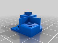
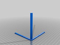
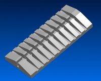
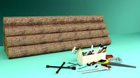
I posted a tool for assessing horizontal expansion a while back that a few people found useful. I've updated it a few times since, so here is the current version I am using now.
Changes include:
added tapered spacers top & bottom on both parts - this prevents top & bottom artefacts / flaring from interfering with the measurement
measures in one axis only - my original tapered-cylinder design effectively measures whichever axis exhibits more HE, and I wondered if there would be a difference in X vs Y (in the end I didn't see any)
"magnification" now 100x - the original was 80x, which made it easier to make a mistake in the mental math if I was in a hurry
The tick-marks are 1 mm apart, with bigger triangles every 5th mm, and each mm of mis-alignment represents 10 microns (0.01 mm) of horizontal expansion. This is the useful limit of resolution at the scale I work in, at this point you're having to make decisions around whether you want to measure with the layers aligned between the two parts vs out of phase, and whether you want to measure fresh off the bed, or after you've slid the parts together a few times and worn the surface down a bit. If the core won't go all the way into the frame, measure off the tick mark at the wider end of the frame; you have positive HE (and therefore need to put a more negative value under "Shell / Horizontal Expansion" in Cura to compensate), if it goes too far in then use the other mark on the frame, and you need to make your HE correction more positive.
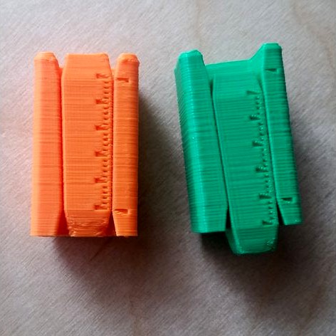
In the attached photo, the orange HIPS print is dialed in just the way I want it. In contrast, the green PLA print has the HE value in CURA set about 45 microns too negative, and the core has gone correspondingly too far in and is coming out the other side.
HE can vary whenever you change settings (especially temperatures), materials etc. Having used this tool to calibrate my Taz6, I keep HE set to -0.070 mm for PLA and -0.120 mm for HIPS, and I expect to be able to print e.g. M6 nuts and bolts that will fit stock hardware and each other on the first attempt. When calibrating, I work the core & frame past each other a few times to get some initial wear before I read the measurement - so if I print a nut and bolt they will be pretty stiff initially, but after they are broken in a bit they screw & unscrew well.
Changes include:
added tapered spacers top & bottom on both parts - this prevents top & bottom artefacts / flaring from interfering with the measurement
measures in one axis only - my original tapered-cylinder design effectively measures whichever axis exhibits more HE, and I wondered if there would be a difference in X vs Y (in the end I didn't see any)
"magnification" now 100x - the original was 80x, which made it easier to make a mistake in the mental math if I was in a hurry
The tick-marks are 1 mm apart, with bigger triangles every 5th mm, and each mm of mis-alignment represents 10 microns (0.01 mm) of horizontal expansion. This is the useful limit of resolution at the scale I work in, at this point you're having to make decisions around whether you want to measure with the layers aligned between the two parts vs out of phase, and whether you want to measure fresh off the bed, or after you've slid the parts together a few times and worn the surface down a bit. If the core won't go all the way into the frame, measure off the tick mark at the wider end of the frame; you have positive HE (and therefore need to put a more negative value under "Shell / Horizontal Expansion" in Cura to compensate), if it goes too far in then use the other mark on the frame, and you need to make your HE correction more positive.
In the attached photo, the orange HIPS print is dialed in just the way I want it. In contrast, the green PLA print has the HE value in CURA set about 45 microns too negative, and the core has gone correspondingly too far in and is coming out the other side.
HE can vary whenever you change settings (especially temperatures), materials etc. Having used this tool to calibrate my Taz6, I keep HE set to -0.070 mm for PLA and -0.120 mm for HIPS, and I expect to be able to print e.g. M6 nuts and bolts that will fit stock hardware and each other on the first attempt. When calibrating, I work the core & frame past each other a few times to get some initial wear before I read the measurement - so if I print a nut and bolt they will be pretty stiff initially, but after they are broken in a bit they screw & unscrew well.
Similar models
thingiverse
free
Extruder Calibration Aid by EE_Maker
...ak-through design that is destine to save mankind, but just a handy gizmo that i thought i'd share. take care and stay safe!
thingiverse
free
Horizontal Expansion Test - Prueba de expansión horizontal by wgcv
...ge the values in cura. the horizontal expansion for the horizontal and the vertical, for the holes use hole horizontal expansion.
thingiverse
free
mm gap gauge by jlawson01
...
i made this for measuring the gaps in a table saw guide slot. caliper tool wasn't fitting in where i needed the measurement.
thingiverse
free
20mm calibration cube with hole 10mm by annu333
...rint setup - custom - shell - horizontal expansion
calculation:
(measured value - 10mm)/2=setting in cura
exam. (9.28-10)/2=-0,36
thingiverse
free

Hole calibration test by sa3aad
...ue to compensate any differences in measurements.
thanks
inspired by chephttps://www.youtube.com/channel/ucsdc_0ztxikarfen2drdjhg
thingiverse
free
Calibration Cube
...tic shrinks as it cools. the ability to control the horizontal expansion is important when you're working with precise sizes.
thingiverse
free
Inner Dimension Calibration Test by the_notalaughingtoaster
...djusting horizontal expansion to get those measurements dialed in.
if you scale, would suggest scaling by whole number factors.
thingiverse
free
Grohe mounting nut alternative by juridzh
... grohe mounting set 48384000.
m33x1.5 thread 12mm long
sliced with cura with pre-calibrated "hole horizontal expansion"
thingiverse
free
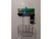
AnyCubic Wash and Cure Wall Mount for Accessories by rianocerous
...dded the individual components i designed, so that you can mix them into something if you need smaller (for resin printers, etc.)
thingiverse
free
50, 100, 110 XYZ Calibration Ruler Minimal by agibson2
... to center.
it is 100 mm center to center of the outer 2 marks.
the overall length is 110mm outside to outside of the long spans.
Marku
turbosquid
free
Markus
... available on turbo squid, the world's leading provider of digital 3d models for visualization, films, television, and games.
turbosquid
free
Cabinet Markus
...d model cabinet markus for download as 3ds, max, obj, and fbx on turbosquid: 3d models for games, architecture, videos. (1174788)
turbosquid
$25
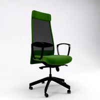
Markus chair
... available on turbo squid, the world's leading provider of digital 3d models for visualization, films, television, and games.
3ddd
$1

Solstice by Markus Johansson
...rkus johansson
3ddd
solstice
светильник solstice
дизайнер markus johanssonhttp://markusjohansson.com/project/solstice/
3ddd
$1
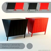
Walking Cabinet by Markus Johansson
... тумба
http://www.contemporist.com/2013/03/26/walking-cabinet-by-markus-johansson/
turbosquid
$39
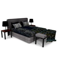
Bed Smania Markus
... 3d model bed smania markus for download as max, obj, and fbx on turbosquid: 3d models for games, architecture, videos. (1289836)
3ddd
free
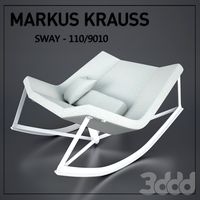
Markus Krauss "SWAY"
... кресло-качалка
markus krauss, sway - 110/9010http://www.markuskrauss.com/shop
3ddd
$1

Markus Large Ottoman
...exture. the model has 3 material presets (tan leather, oxford grey leather, and grey fabric)
dimension: 965mm diameter x h 460mm
turbosquid
$20

ikea Markus Chair and Office Table Pack
...l ikea markus chair and office table pack for download as max on turbosquid: 3d models for games, architecture, videos. (1215135)
3d_export
$10
MARKUS IKEA chair
...~ 100,000 model parts: 1 texture format: .png .jpg resolution: 1024*1024 pbr in substance painter formats: .obj .gltf .fbx .blend
V4
design_connected
$16

V4 vases
...v4 vases
designconnected
sy design v4 vases computer generated 3d model. designed by song, seung-yong.
turbosquid
$20
Door v4
...yalty free 3d model door v4 for download as max, max, and obj on turbosquid: 3d models for games, architecture, videos. (1523140)
turbosquid
$5
Hand v4
...yalty free 3d model hand v4 for download as ztl, obj, and stl on turbosquid: 3d models for games, architecture, videos. (1567431)
turbosquid
$9
silencer v4
...3d model silencer v4 for download as blend, dae, fbx, and obj on turbosquid: 3d models for games, architecture, videos. (1711410)
turbosquid
$90

V4 Engine
... available on turbo squid, the world's leading provider of digital 3d models for visualization, films, television, and games.
turbosquid
$35
Payphone v4
... available on turbo squid, the world's leading provider of digital 3d models for visualization, films, television, and games.
turbosquid
$28

HAZRO V4
... available on turbo squid, the world's leading provider of digital 3d models for visualization, films, television, and games.
turbosquid
$15
Carousel v4
... available on turbo squid, the world's leading provider of digital 3d models for visualization, films, television, and games.
turbosquid
$1
PokBall V4
... available on turbo squid, the world's leading provider of digital 3d models for visualization, films, television, and games.
3ddd
free

фонтан V4
...фонтан v4
3ddd
фонтан
фонтан, fantan, fontan
Calibration
turbosquid
$15
DEFIBRILLATOR CALIBRATORS
... available on turbo squid, the world's leading provider of digital 3d models for visualization, films, television, and games.
turbosquid
$3
Calibration Test Benches
...libration test benches for download as 3ds, obj, c4d, and fbx on turbosquid: 3d models for games, architecture, videos. (1355804)
turbosquid
$79

Tag Heuer Monaco Calibre 11
...free 3d model tag heuer monaco calibre 11 for download as max on turbosquid: 3d models for games, architecture, videos. (1634427)
turbosquid
$50
Smith & Wesson 50 Calibre Magnum
... available on turbo squid, the world's leading provider of digital 3d models for visualization, films, television, and games.
3d_export
$10
Laboratory Calibration Weight Set 1 3D Model
... 3d model
3dexport
laboratory lab science equipment weight set
laboratory calibration weight set 1 3d model bessoo 88084 3dexport
3d_export
$15
Laboratory Scale and Calibration Weight Set 3D Model
...port
laboratory lab science equipment weight set scale
laboratory scale and calibration weight set 3d model bessoo 88203 3dexport
3d_export
$5
3D printer filament calibration tool 3D Model
...ernier
3d printer filament calibration tool 3d model download .c4d .max .obj .fbx .ma .lwo .3ds .3dm .stl locoman 107942 3dexport
3d_export
$59

tag heuer link calibre 16 watch
...built to real-world scale. units used: centimeters. model is 18 centimeters tall.<br>scene objects are organized by groups.
3d_export
free
laser height reference calibration tool opt lasers
...ind out more about the engraving and cutting laser heads, this item was designed to work with, take a look at the following page:
3d_export
$99
Patek Philippe White Gold Calibre 89
...br>please note: this 3d model like all my other models cannot be used as nft, as is or modified<br>thank you for reading
Expansion
turbosquid
$42

Expansion tank
...d model expansion tank for download as 3ds, max, obj, and fbx on turbosquid: 3d models for games, architecture, videos. (1207393)
3d_export
$50

Expansion Joint 3D Model
...expansion joint 3d model
3dexport
expansion joint 3d model stargazer 4537 3dexport
turbosquid
$25
Titanic Expansion Joint
... available on turbo squid, the world's leading provider of digital 3d models for visualization, films, television, and games.
3d_export
$5
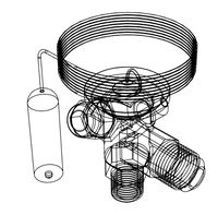
thermostatic expansion valve
...thermostatic expansion valve
3dexport
3d model stl of fusion 360.
3d_ocean
$15
Dungeon Tileset01 Expansion 1
...m/dungeon-tileset01-base/4625640 including stairs, tiles to make large rooms and a new texture that works with the tiles in th...
turbosquid
$20
Cartoon Corgi Banana Costume Expansion Pack
...artoon corgi banana costume expansion pack for download as ma on turbosquid: 3d models for games, architecture, videos. (1445388)
3ddd
$1

Hichory chair Ingold Oval Expansion
...kitchen-furniture/1911-collection/i510089-ingold-oval-expansion-top-mahogany-and-185-11-ingold-3-leg-pedestal-base.aspx
turbosquid
$299
Sci-Fi Dark Space Game Kit plus Expansion Pack
... available on turbo squid, the world's leading provider of digital 3d models for visualization, films, television, and games.
3d_export
$5
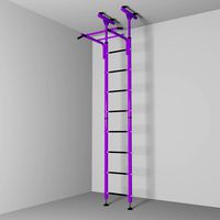
Swedish wall
...swedish wall 3dexport swedish wall, expansion wall bars, stairs for children, horizontal bar for...
3d_export
$10

External HDD 3D Model
...hard disk drive external seagate usb storage hdd portable expansion data mobile external hdd 3d model nkfrds 47740...
Horizontal
3ddd
$1
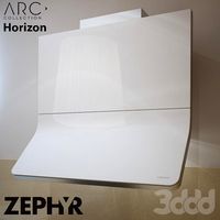
Zephyr Horizont
...zephyr horizont
3ddd
вытяжка , zephyr
вытяжка zephyr horizont
design_connected
$13
Mr.Tubes Horizontal
...mr.tubes horizontal
designconnected
tonone mr.tubes horizontal computer generated 3d model.
3d_export
$5

Horizontal bars
...orizontal bars
3dexport
this is a large horizontal bar for rhythmic gymnastics, as well as for pull-ups and many other exercises
3d_export
$5
Horizontal circular saw
...horizontal circular saw
3dexport
horizontal circular saw
turbosquid
$13

Horizontal tank
...id
royalty free 3d model horizontal tank for download as fbx on turbosquid: 3d models for games, architecture, videos. (1709417)
turbosquid
$1

Decor horizontal
...
royalty free 3d model decor horizontal for download as sldpr on turbosquid: 3d models for games, architecture, videos. (1256236)
3ddd
free
tiling horizontal decoratives
...tiling horizontal decoratives
3ddd
штукатурка
tiling horizontal decorative texture
turbosquid
$19
The horizontal bar
... model the horizontal bar for download as , fbx, stl, and obj on turbosquid: 3d models for games, architecture, videos. (1684719)
turbosquid
$10

Horizontal Bar
...ree 3d model horizontal bar for download as max, obj, and fbx on turbosquid: 3d models for games, architecture, videos. (1435728)
turbosquid
$15
Horizontal Bar
...d model horizontal bar for download as 3ds, max, obj, and fbx on turbosquid: 3d models for games, architecture, videos. (1317823)
0
turbosquid
$12
Calligraphic Digit 0 Number 0
...hic digit 0 number 0 for download as max, obj, fbx, and blend on turbosquid: 3d models for games, architecture, videos. (1389318)
3d_export
$6
set-0
...set-0
3dexport
turbosquid
$6

hedge 0
...yalty free 3d model hedge 0 for download as max, obj, and fbx on turbosquid: 3d models for games, architecture, videos. (1450353)
turbosquid
$5

Nuber 0
...oyalty free 3d model nuber 0 for download as ma, obj, and fbx on turbosquid: 3d models for games, architecture, videos. (1564674)
turbosquid
$22

0.jpg
... available on turbo squid, the world's leading provider of digital 3d models for visualization, films, television, and games.
turbosquid
free

Steam Locomotive Fowler 4F 0-6-0
... available on turbo squid, the world's leading provider of digital 3d models for visualization, films, television, and games.
turbosquid
$10

Liquid Number 0
... model liquid number 0 for download as c4d, 3ds, fbx, and obj on turbosquid: 3d models for games, architecture, videos. (1689919)
turbosquid
$45
Dragon360_perspShape_tmp.0.jpg
... available on turbo squid, the world's leading provider of digital 3d models for visualization, films, television, and games.
turbosquid
$8

Rocks Debris 0
... available on turbo squid, the world's leading provider of digital 3d models for visualization, films, television, and games.
3d_export
$18
wood-guardrail-fence 0
...wood-guardrail-fence 0
3dexport
wood-guardrail-fence 0<br>3ds max 2015
Tool
turbosquid
$21
Tool box with tools
... available on turbo squid, the world's leading provider of digital 3d models for visualization, films, television, and games.
archibase_planet
free
Tools
...tools
archibase planet
tools instruments implements
tools n070114 - 3d model (*.gsm+*.3ds+*.max) for interior 3d visualization.
3d_ocean
$12
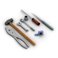
Tools
...tools
3docean
hammer metal old screw tools wrench
maya
turbosquid
$6

Tool Cart / Tool Box
...
royalty free 3d model tool cart / tool box for download as on turbosquid: 3d models for games, architecture, videos. (1241859)
3d_ocean
$15
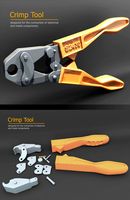
crimp tool
... tool copper cutter crimp crimp tool electrical electrical tools press tools pressing tool tools wire cutter
created in maya 2013
3d_ocean
$5

Tools
...tools
3docean
3d models paint tools work
3d,models,works,paint,art,create,working,
3d_export
free
tools
...tools
3dexport
coldsteel
turbosquid
$15
Tools
...turbosquid
royalty free 3d model tools for download as blend on turbosquid: 3d models for games, architecture, videos. (1331352)
3ddd
$1
bar tool
...bar tool
3ddd
барный
bar tool
turbosquid
$35

tools
... available on turbo squid, the world's leading provider of digital 3d models for visualization, films, television, and games.