Thingiverse

HF Vertical Antenna Freestanding Loading Coil by Chetmystery
by Thingiverse
Last crawled date: 3 years, 1 month ago
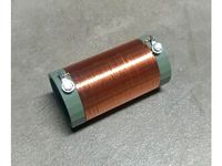
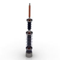
Free-standing manually adjusted loading coil form for amateur radio use on the HF bands.
This will give a maximum inductance of about 19 microhenries and is designed to interface with standard 3/8"-24 antenna stud hardware, mounts, an whips.
You'll need to print the coil form, two of the end caps, one of the rings for the shorting point, and two of the small set screws used to set the ring on the coil. I recommend printing the end caps with 100% infill to make them solid, otherwise when you add the mounting hardware to them you'll compress and weaken the plastic, leading to a broken coil down the line. Also print the thumb screws with full infill, just to make them more durable.
In addition to these printed parts, you'll need the following:
For mounting the whip on top of the coil, one 3/4" long 3/8"-24 bolt with washers, lock washer and a long coupling nut. (these parts can all be bout as a set used for mounting CB antennas such as this (remove the plastic insulator ring parts): https://www.amazon.com/dp/B000X380KQ/
For mounting the bottom of the coil to a standard stud antenna mount, a second set of the parts above except consider going with a slightly longer 3/8"-24 bolt and use a standard lower-profile nut.
1mm diameter stainless steel, uncoated wire for wrapping the coil. You can find small spools of this at most hardware stores in the aisle that sells picture wall-hanging hardware.
A small #8-32 screw or bolt with washers and a matching "acorn nut". These parts act as the shorting tap on the ring and the acorn nut's rounded tip will be what touches and shorts to the coil inside that ring.
About 10 inches of flexible coated wire as the shorting lead
A handful of ring terminals for the coil wire and shorting wire that fit the 3/8" and #8-32 bolts.
Super glue to attach the caps to the coil.
To build, begin by drilling 3 small holes at each end of the grove molded in the coil form for the coil wire, this is to pass the wire in and out and in on each end for strain relief. Wind the coil tightly by hand and leave a few inches of wire on each end after the strain relief holes, the ends of the wire should be on the inside of the coil. Crimp on a ring terminal on each end that fits the 3/8" stub bolts, and attach the bolts to the end caps, tightening down the hardware well. once the parts are all secure to the caps, install them to the coil body and secure with super glue. At this point, the coil should be wound and each end of the coil wire secured to the studs on the inside of the caps that you just glued on. Attach the shorting lead to the stub bolt on the bottom of the coil and the #8-32 bolt on the shorting collar. Slip the collar ring over the coil and use the two printed thumb screws in the printed threaded hols on the ring to lock it in place on the coil. Loosen these thumb screws to move the shorting ring up and down.
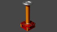
Now you can add any whip element to the top of the coil and screw the bottom to any stud antenna mount. Add a ground and/or radials and attach your coax and tune the coil to your desired frequency. With a 10-foot whip on top, there should be enough loading in the coil to tune down to 7MHz and up.
This will give a maximum inductance of about 19 microhenries and is designed to interface with standard 3/8"-24 antenna stud hardware, mounts, an whips.
You'll need to print the coil form, two of the end caps, one of the rings for the shorting point, and two of the small set screws used to set the ring on the coil. I recommend printing the end caps with 100% infill to make them solid, otherwise when you add the mounting hardware to them you'll compress and weaken the plastic, leading to a broken coil down the line. Also print the thumb screws with full infill, just to make them more durable.
In addition to these printed parts, you'll need the following:
For mounting the whip on top of the coil, one 3/4" long 3/8"-24 bolt with washers, lock washer and a long coupling nut. (these parts can all be bout as a set used for mounting CB antennas such as this (remove the plastic insulator ring parts): https://www.amazon.com/dp/B000X380KQ/
For mounting the bottom of the coil to a standard stud antenna mount, a second set of the parts above except consider going with a slightly longer 3/8"-24 bolt and use a standard lower-profile nut.
1mm diameter stainless steel, uncoated wire for wrapping the coil. You can find small spools of this at most hardware stores in the aisle that sells picture wall-hanging hardware.
A small #8-32 screw or bolt with washers and a matching "acorn nut". These parts act as the shorting tap on the ring and the acorn nut's rounded tip will be what touches and shorts to the coil inside that ring.
About 10 inches of flexible coated wire as the shorting lead
A handful of ring terminals for the coil wire and shorting wire that fit the 3/8" and #8-32 bolts.
Super glue to attach the caps to the coil.
To build, begin by drilling 3 small holes at each end of the grove molded in the coil form for the coil wire, this is to pass the wire in and out and in on each end for strain relief. Wind the coil tightly by hand and leave a few inches of wire on each end after the strain relief holes, the ends of the wire should be on the inside of the coil. Crimp on a ring terminal on each end that fits the 3/8" stub bolts, and attach the bolts to the end caps, tightening down the hardware well. once the parts are all secure to the caps, install them to the coil body and secure with super glue. At this point, the coil should be wound and each end of the coil wire secured to the studs on the inside of the caps that you just glued on. Attach the shorting lead to the stub bolt on the bottom of the coil and the #8-32 bolt on the shorting collar. Slip the collar ring over the coil and use the two printed thumb screws in the printed threaded hols on the ring to lock it in place on the coil. Loosen these thumb screws to move the shorting ring up and down.
Now you can add any whip element to the top of the coil and screw the bottom to any stud antenna mount. Add a ground and/or radials and attach your coax and tune the coil to your desired frequency. With a 10-foot whip on top, there should be enough loading in the coil to tune down to 7MHz and up.
Similar models
thingiverse
free
110uH Loading Coil Form for Short EFHW Antenna by Chetmystery
...terminals and 4mm bolts/hardware. second 4.5mm hole on each end can be used to loop antenna wire through to allow strain relief.
3dwarehouse
free

Hardware-1/4'; Nuts & Bolts, Adjustable Length
...s and nuts (respectively) to other end; tighten. simple, low-poly graphically effective component. #bolts #hardware #nuts #washer
thingiverse
free

Adjustable Leg Leveler by hauser
...with a 3/8" nut welded into each end. after my friend welded the nuts in, i cleaned them with acetone and painted them gray.
thingiverse
free

WAXTENNA PRD (Portable Rotatable Dipole) by VA3TNE
...folding antennas, or two 9' long telescoping whip antenna's similar to the ones sold by buddi-pole, you can have...
thingiverse
free

Flexible Solar Panel Mount by mrjadkowski
...plication.
print these upside down (i.e. you should be able to see the hex-shaped inset for the bolt head on top when you print).
grabcad
free

Reel Holder for large coils
...holder for large coils
grabcad
external ⌀300
interior ⌀40...75
you need:
4 bearing 22*8*7
3 screw studs м8*250
nut and washer
thingiverse
free

Target Hardware Holder by EldronMaker
...r to hang two gongs.
4x 3/8" bolts up to 2.5"
4x 3/8" bolts up to 1.5"
8x 3/8" nuts
6x 1.5" washers
thingiverse
free

Jeep Door Storage Hanger by Mframe
... plate 180 degrees if your stud is to the left or right. the slots should allow you to fine adjust the latch position if needed.
thingiverse
free

Power Distribution Block
...t, washer, nut, lock washer. top attaches with 10-24 hardware (x6). can be mounted with screws or 10-24 hardware from inside (x3)
thingiverse
free

Monitor wallmount using 2020 extrusions by darookee
...nitor you can also use 20x20-arm-bracket-short and/or 20x20-arm-attachment-short, but the longer versions seem to be more stable.
Chetmystery
thingiverse
free

T-50 Torroid Antenna Trap by Chetmystery
....
t-50 sized torroids will be pretty small, so be aware of power limitations in traps of this size, best served for qrp use only.
thingiverse
free

49:1 EFHW 1x FT140 Transformer Box by Chetmystery
...ired for strain relief of the antenna wire or for hanging the box.
lid may be secured with a few drops of super glue or hot glue.
thingiverse
free

49:1 EFHW 2x FT140 Transformer Box by Chetmystery
...ole key'ed to make assembly easier. also added small pry points on the lid to allow future removal after gluing if required.
thingiverse
free
110uH Loading Coil Form for Short EFHW Antenna by Chetmystery
...terminals and 4mm bolts/hardware. second 4.5mm hole on each end can be used to loop antenna wire through to allow strain relief.
Hf
cg_studio
$50

Canon HF S213d model
...era cam digital video handcam lens
.max - canon hf s21 3d model, royalty free license available, instant download after purchase.
3ddd
$1

Aventos HF. Подьемник складной Blum.
...подьемный механизм aventos hf, blum, австрия. 5354 полигонов, текстуры, инструкция.http://www.blum.com/ru/ru/01/10/10/
turbosquid
$100

HF nU gun .blend
... available on turbo squid, the world's leading provider of digital 3d models for visualization, films, television, and games.
3d_export
$99

Lancia Stratos HF 3D Model
...ally photorealistic speed people drive championship italy italia italian munari
lancia stratos hf 3d model fabelar 70549 3dexport
cg_studio
$49

Lancia Delta HF integrale3d model
... model
cgstudio
.3ds .max - lancia delta hf integrale 3d model, royalty free license available, instant download after purchase.
turbosquid
$55

Lancia Fulvia HF 4WD concept
...ee 3d model lancia fulvia hf 4wd concept for download as wire on turbosquid: 3d models for games, architecture, videos. (1310343)
3d_export
$129

Lancia Stratos HF 1974 3D Model
...ly sport racing rallye car fast group oldtimer classic retro vintage antique
lancia stratos hf 1974 3d model squir 38155 3dexport
cg_studio
$129

Lancia Stratos HF 19743d model
....3ds .c4d .fbx .lwo .max .obj - lancia stratos hf 1974 3d model, royalty free license available, instant download after purchase.
3d_export
$24

lancia delta hf integrale
...the detail and realism of any of your rendering projects.<br>available 3d file format: max2013, v-ray render, fbx, obj, 3ds
turbosquid
$16

Canon HF-DC2 High-Power
...canon hf-dc2 high-power for download as ma, max, fbx, and dae on turbosquid: 3d models for games, architecture, videos. (1202334)
Freestanding
3ddd
$1

Freestanding Ranges V36B6
...freestanding ranges v36b6
3ddd
плита
профессиональная газовая плита freestanding ranges v36b6
3ddd
$1

Mobile lavabo freestanding
...mobile lavabo freestanding
3ddd
mobile lavabo freestanding , тумба
размер 141*75*50
turbosquid
$29

Freestanding Bath
... available on turbo squid, the world's leading provider of digital 3d models for visualization, films, television, and games.
turbosquid
$7

Freestanding Sink
... available on turbo squid, the world's leading provider of digital 3d models for visualization, films, television, and games.
3ddd
$1

Maison Valentina Koi Freestand
...meter: 45 cm | 17,72"
height: 90 cm | 35,43"http://www.maisonvalentina.net/products/freestands/koi-freestand/
3d_ocean
$6

Freestanding, Modern Bathtub_No_02
...op into any scene or be used as a stand-alone prop. material setup is not included. professional quality model designed for ea...
3d_ocean
$5

Freestanding, Modern Bathtub_No_07
...op into any scene or be used as a stand-alone prop. material setup is not included. professional quality model designed for ea...
3d_ocean
$5

Freestanding, Modern Bathtub_No_03
...op into any scene or be used as a stand-alone prop. material setup is not included. professional quality model designed for ea...
3d_ocean
$5

Freestanding, Modern Bathtub_No_05
...op into any scene or be used as a stand-alone prop. material setup is not included. professional quality model designed for ea...
3d_ocean
$5

Freestanding, Modern Bathtub_No_06
...op into any scene or be used as a stand-alone prop. material setup is not included. professional quality model designed for ea...
Coil
3d_export
$5
Tesla coil
...tesla coil
3dexport
detailed tesla coil model
archibase_planet
free

Fan coil
...fan coil unit air conditioning daikin conditioner
fan coil daikin n160915 - 3d model (*.gsm+*.3ds) for exterior 3d visualization.
cg_studio
$20

Coiled Rope3d model
...pe lasso coil bustermk2 coiled cord
.max - coiled rope 3d model, royalty free license available, instant download after purchase.
turbosquid
$8

Tesla Coil
...bosquid
royalty free 3d model tesla coil for download as fbx on turbosquid: 3d models for games, architecture, videos. (1458990)
turbosquid
$29

Mosquito Coil
...oyalty free 3d model mosquito coil for download as ma and obj on turbosquid: 3d models for games, architecture, videos. (1263002)
turbosquid
$2

electronic coil
...y free 3d model electronic coil for download as obj and blend on turbosquid: 3d models for games, architecture, videos. (1503485)
turbosquid
$2
ferrite coil
...alty free 3d model ferrite coil for download as blend and obj on turbosquid: 3d models for games, architecture, videos. (1588248)
turbosquid
$15
Tesla Coil
... available on turbo squid, the world's leading provider of digital 3d models for visualization, films, television, and games.
turbosquid
$10

coil gun
... available on turbo squid, the world's leading provider of digital 3d models for visualization, films, television, and games.
turbosquid
$4

The transition coil
... available on turbo squid, the world's leading provider of digital 3d models for visualization, films, television, and games.
Antenna
archibase_planet
free
Antenna
...chibase planet
antenna aerial television antenna
antenna kathrein n090913 - 3d model (*.gsm+*.3ds) for exterior 3d visualization.
archibase_planet
free
Antenna
...antenna
archibase planet
satellite antenna
antenna 1 - 3d model (*.gsm+*.3ds) for exterior 3d visualization.
archibase_planet
free
Antenna
...antenna
archibase planet
equipment satellite antenna
antenna 2 - 3d model (*.gsm+*.3ds) for exterior 3d visualization.
archibase_planet
free
Antenna
...ntenna
archibase planet
satellite antenna equipment dish aerial
antenna 3 - 3d model (*.gsm+*.3ds) for exterior 3d visualization.
archibase_planet
free
Antenna
...antenna
archibase planet
satellite antenna dish dish aerial
antenna 4 - 3d model (*.gsm+*.3ds) for exterior 3d visualization.
archibase_planet
free
Antenna
...e planet
antenna dish dish aerial
antenna c-band satellite s180-g n210612 - 3d model (*.gsm+*.3ds) for exterior 3d visualization.
3d_export
$5

car antenna
...car antenna
3dexport
car antenna, antenna, car gadgets
turbosquid
$1

antenna
...rbosquid
royalty free 3d model antenna for download as blend on turbosquid: 3d models for games, architecture, videos. (1655786)
3d_export
free

Station with antenna
...station with antenna
3dexport
station with antenna
turbosquid
$5

Antenna
...id
royalty free 3d model antenna for download as max and fbx on turbosquid: 3d models for games, architecture, videos. (1381532)
Loading
3ddd
$1

Billiani Load
...billiani load
3ddd
billiani , load
стулья load итальянской фабрики load
turbosquid
$5

Wheelbarrow loaded
...id
royalty free 3d model wheelbarrow loaded for download as on turbosquid: 3d models for games, architecture, videos. (1615308)
turbosquid
$15
Dummy Load
...odel dummy load for download as 3ds, obj, fbx, blend, and dae on turbosquid: 3d models for games, architecture, videos. (1363932)
turbosquid
$3

Load-limitroadsign
...oad-limitroadsign for download as 3ds, dae, fbx, obj, and stl on turbosquid: 3d models for games, architecture, videos. (1532902)
3d_export
$79

iveco daily loading
...iveco daily loading
3dexport
iveco daily loading 3d model. include max, obj, fbx files.
3d_export
$9

automatic loading and unloading punch
...automatic loading and unloading punch
3dexport
automatic loading and unloading punch
3d_export
$19
concrete loading ramp
...te loading ramp
3dexport
concrete loading ramp 3d model. real-time ready, multiple import formats<br>thank you for reading
turbosquid
$1

Front Load Dumpster
...free 3d model front load dumpster for download as obj and fbx on turbosquid: 3d models for games, architecture, videos. (1694510)
turbosquid
$45

AGV to Container Load
... model agv to container load for download as ma, obj, and fbx on turbosquid: 3d models for games, architecture, videos. (1589627)
turbosquid
$20

Pelican Loading Center
... available on turbo squid, the world's leading provider of digital 3d models for visualization, films, television, and games.
Vertical
3ddd
$1
Vertical curtain
...vertical curtain
3ddd
роллеты
vertical curtain
modern curtain
design_connected
$11

Mr.Tubes Vertical
...mr.tubes vertical
designconnected
tonone mr.tubes vertical computer generated 3d model.
3ddd
free

Vertical gardening
... фитомодуль , фитостена
vertical gardening
2000x1000x165
vizpark
$5

Einstein Vertical
...tical is a set of 3d brick textures for modern buildings, including mulit-textures and 4k tileable textures with material layers.
turbosquid
$5

brazier vertical
... free 3d model brazier vertical for download as sldas and ige on turbosquid: 3d models for games, architecture, videos. (1647570)
turbosquid
$18
Vertical blinds
...ee 3d model vertical blinds for download as max, obj, and fbx on turbosquid: 3d models for games, architecture, videos. (1604868)
3d_export
$40

vertical stirling engine
...vertical stirling engine
3dexport
vertical stirling engine
turbosquid
$6
vertical fence
...d model vertical fence for download as c4d, 3ds, dxf, and obj on turbosquid: 3d models for games, architecture, videos. (1571631)
turbosquid
$50

Vertical Garden
... available on turbo squid, the world's leading provider of digital 3d models for visualization, films, television, and games.
turbosquid
$20

vertical flag
... available on turbo squid, the world's leading provider of digital 3d models for visualization, films, television, and games.