GrabCAD
Heliostat with Adjustable Flatness Control
by GrabCAD
Last crawled date: 1 year, 11 months ago
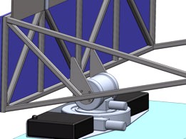
This mobile heliostat uses a spring-tempered stainless-steel sheet for its mirror.
In the stored state, the mirror is rolled into a large diameter coil. This puts potential energy into the material. Cables connected to brake-motors hold this position. The generous large curvature of the coil allows the mirror and its structural “tape springs” to stay coiled while remaining well above the material yield points. Said another way, the "spring" free state of the mirror (which is extended and slightly concave) is maintained, and the amount of stress relaxation occurring during storage time is managed.
The deployment of the mirror is a slow and controlled “un-furling” towards the mirror’s free state. Cables connected to rotary dampers, are let out by brake motors to provide this controlled motion. The free, or natural, state of the mirror is slightly concave, which ensures the cables are always in tension during and after deployment.
When deployment is complete, the cable system provides control and fine-tuning of the mirror's "shape". The mirror can be made perfectly flat, or, it can be made slightly concave or convex which would allow focusing or dispersion of the reflected light if desired. After shape adjustments are made, spring-loaded brakes "lock in" the position of the cables and the brake-motors are powered off. This is for the sake of energy efficiency, ensuring that energy is no longer consumed after tuning is complete.
This system provides many benefits over hinged panel and inflatable designs because it is simple, robust, and allows active control over the flatness of the entire mirror. Fabrication tolerances, stress relaxation, creep, thermal expansion, damage, etc., in hinged joint could render a heliostat system inoperable, because all panels would not be perfectly flat to each other. Similarly, inflatable designs risk losing gas pressure due to permeation through bulk material, imperfect seals, degradation caused by solar radiation, or damage from micrometeorites. Pressure loss in an inflatable structure would cause the system to “sag” and lose its shape which would render the entire system non-functional – patching and recharging with new compressed air is difficult in space. The proposed design manages environmental risks well because it is robust and adaptable, it can physically stand up to the large variety of hazards and abuse which it is likely to encounter in space.
The structural support for the mirror is provided by side bends and “tape springs” along the edges and back of mirror. “Tape springs” are thin strips of steel with curved cross sections, they can be coiled up, and they also provide stiffness when extended (they are a common design used in tape measure blades, however note that the “tape springs” in this design are much stronger than a tape measure, also there is no recoil spring.) Additional structure is provided by square tubes mounted across the top and bottom of the mirror. These tubes provide the (horizontal) stiffness and flatness to the mirror.
The presented design fits inside the allowed envelope when retracted and provides over 10 m^2 of flat reflecting surface when deployed. However, without these constraints the concept is easily scalable to larger or smaller sizes, or to different aspect ratios (wider instead of taller for example). For increased mirror sizes, additional horizontal support can be added in the form of battens spot welded or riveted across the back of the mirror at incrementing heights. Additional cables systems could be added to these battens if even more shape control is desired. Similarly, vertical stiffness can be increased by adding additional or increasing thickness of the “tape springs”.
Pitch and yaw tracking motion is produced by a two-axis slew drive, which is connected to control system including a sun sensor. Slew motors are robust and simple devices already proven to work well for heliostats here on earth. A separate benefit to using these is that they allow the active motors and controls to be located near each other. This allows for simplified thermal management as the entire area can be covered by insulative blankets. Waste heat from the motors can be trapped and used to help maintain temperatures as opposed to being lost via radiation into space.
The overall system has low mass and a low rotational inertia with respect to the rover, due to the mirror in large part “supporting itself”. This makes for reduced rocket fuel required for transport, and allows for movement across the lunar surface while deployed.
The heliostat includes 1.12 m^2 of solar panels below the mirror, and battery energy storage. This provides the power to the motors, controls, and heat management systems.
Supplemental benefits of this design:
- The energy of the springs, which is released as the mirror unfurls, can optionally be used to deploy leg support mechanisms. This would be useful for stand-alone heliostats not mounted to rovers.
- In addition to being flat, the mirror can be adjusted to be slightly convex or slightly concave. As mentioned previously, this grants the ability to increase or decrease the reflected light intensity if needed for different applications.
See the attached PDF files for more engineering details of this concept. Also, I welcome and would be very happy to answer any questions.
Similar models
grabcad
free

Lunar Torch
...battens tack welded across the back of the mirror. similary, vertical stiffness can be increased by adding "tape springs"...
grabcad
free

Non-Motorized-Deployment Heliostat
... entire package can be scaled down to fit into or onto a rover. more mirrors can be added to make up for reduced reflecting area.
grabcad
free

Lunar Torch with inflatable structure
...in opposition at the mirror film there is a similar system of tie rods. with the inflatable chambers deflated...
grabcad
free

Lunar Torch with inflatable structure
...in opposition at the mirror film there is a similar system of tie rods. with the inflatable chambers deflated...
grabcad
free

Mobile Circular Heliostat
...the photos attach show the mirrors at different stages of deployment. the entire mirror can also rotate in 3 different directions
grabcad
free

Self-Deploying Heliostat System based on a Spring made out of Shape Memory Polymers
...eployable concept idea
https://www.youtube.com/watch?v=fgwnqu0t2ou
locking mechanism
https://www.youtube.com/watch?v=vlcqlceecb8
grabcad
free

Lunar Heliostat
...sing lens. the torch can be rotated through x ,y and z axis, which helps the rover to redirect the solar energy wherever needed.
grabcad
free

ALLGO MONOGO light lifting system
...is the optimal solution taking into account the lunar, lifting and on-board weight constraints.
let's trust this system!
🌙🚀👌
grabcad
free

Press Coil Spring Machine
... hmi control input data, qualification can check distance coil spring and can separate coil spring ng and ok in the fastest time.
grabcad
free

Lunar heliostat
...all motor inside every central tube is used for reeling tape while stowing heliostat. the structure is easily scalable in height.
Heliostat
3d_export
$199
Solar Power Plant 3D Model
...plant 3d model 3dexport solar power plant industrial helios heliostat modern energy station tower sun panel farm solar power...
thingiverse
free

Heliostat by DamianPaton
...cale from the heliostat by arisolar (all right reserved). this model shows the new 2 axis motion system (spinning and elevation).
thingiverse
free
Conie the Heliostat by Cod
...e it is rain protected.
stepper motore i've used 42byghw208. for use with inductive limit switches(lj12a3-4-z/by)
have fun!
thingiverse
free

Heliostat Solar Sensor support structure by Daedelus
...nting at the brightest spot.
the two parts are superglued together so that the smaller part functions as an attachment bracket.
thingiverse
free
Pan Tilt Mechanism for 28BYJ-48 Motors by zimirken
...towards an ideal design for a heliostat. speaking of heliostat, included is a mounting bracket for a mirror or...
thingiverse
free

solar sensor one axis by arduinomastercomau
...upload another design that is more suitable for a heliostat ...
free3d
$30

TURBOSPAIN SOLAR PLANT
...it uses an array of flat, movable mirrors (called heliostat) to focus the sun's rays upon a collector tower...
thingiverse
free
Mars Habitat Concept by sjwaldron
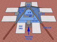
...dual solar collection system, both solar power tower with heliostat and photovoltaic type devices would be...
grabcad
free

lunar heliostat
...lunar heliostat
grabcad
lunar heliostat
cg_trader
$33

AT heliostat
...g formula’s. see the 'purchasing_the_models' link at appropedia's at_cad_team for additional information on the model
Flatness
3ddd
free
Nurus - Flat
...nurus - flat
3ddd
nurus
nurus - flat
turbosquid
$139

Flat
... available on turbo squid, the world's leading provider of digital 3d models for visualization, films, television, and games.
turbosquid
$20

flat
... available on turbo squid, the world's leading provider of digital 3d models for visualization, films, television, and games.
3d_ocean
$5

Flat TV
...ics hd tv lcd / plasma / flat screen tv
flat tv 3d models. flat tv, contemporary styling and low poly count. the tv has to render
3ddd
$1
Tresse Flat
... tresse
производитель tresse
модель flat
в архиве присутствует версия с материалами для corona
design_connected
$18
Chaise Flat
...chaise flat
designconnected
decameron chaise flat computer generated 3d model. designed by ferreira, marcus.
design_connected
$25
Flat sofa
...flat sofa
designconnected
gandia blasco flat sofa computer generated 3d model. designed by ruiz, mario .
design_connected
$18
Flat armchair
...flat armchair
designconnected
gandia blasco flat armchair computer generated 3d model. designed by ruiz, mario .
design_connected
$16
Flat chair
...flat chair
designconnected
gandia blasco flat chair computer generated 3d model. designed by ruiz, mario .
design_connected
$9
Flat pouf
...flat pouf
designconnected
gandia blasco flat pouf computer generated 3d model. designed by ruiz, mario .
Control
3d_ocean
$4
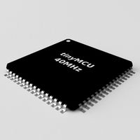
Controller TQFP32
...qfp32
3docean
chip controller cpu electronic gpu mcu micro controller silicon smd tqfp wafer
a micro controller in tqfp32 package
3d_ocean
$4
Controller TQFP44
...44
3docean
chip controller cpu electronic gpu mcu micro controller package smd tqfp tqfp44
a micro controller in a tqfp44 package
3d_export
$15
control unit
...control unit
3dexport
control unit
3ddd
$1
Yacht control
...yacht control
3ddd
yacht control
3d_export
$5
controle pgdm
...controle pgdm
3dexport
carcaca controle pgdm
turbosquid
free
controler
... available on turbo squid, the world's leading provider of digital 3d models for visualization, films, television, and games.
3ddd
$1
Control
...
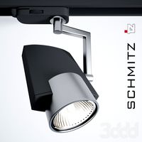
http://www.schmitz-leuchten.de/html-ru/einzelleuchten-lampentyp-details.php?lamptype_no=700&group;=917&id;=731
3d_ocean
$4

Controller TQFP100
...100
3docean
chip computer cpu electronic gpu mcu micro controller pin platine silicon wafer
a micro controller in tqfp100 package
3d_ocean
$4
Controller TQFP64
...qfp64
3docean
chip computer cpu gpu mcu micro controller package silicon tqfp tqfp64 wafer
a micro controller in a tqfp64 package
3d_ocean
$7

Remote controller
... control switcher tv remote
remote controller for tv, sound systems etc easy to edit textures photo real rendered with mental ray
Adjustable
3d_ocean
$7
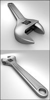
Adjustable Wrench
...adjustable wrench
3docean
adjustable wrench highly detailed wrench
highly detailed adjustable wrench.
3ddd
$1
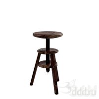
Adjustable Stool
...adjustable stool
3ddd
табурет
wooden adjustable stool.
3d_ocean
$20

Adjustable Gym Bench
...st adjustable bench black equipement gym gymnastic indoor silver sport workout
3d model of black and silver adjustable gym bench.
3d_ocean
$20
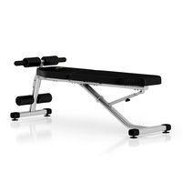
Adjustable Gym Bench
...st adjustable bench black equipement gym gymnastic indoor silver sport workout
3d model of black and silver adjustable gym bench.
3d_ocean
$16

Adjustable Weight Bench
...arbell bench black equipement gym gymnastic indoor sport weight workout
3d model of black adjustable weight bench with a barbell.
turbosquid
$5

Adjustable wrench
...
royalty free 3d model adjustable wrench for download as fbx on turbosquid: 3d models for games, architecture, videos. (1313414)
3d_export
$5
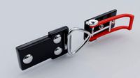
adjustable tension lock
...adjustable tension lock
3dexport
adjustable tension lock
turbosquid
$1

Adjustable Wrench
...free 3d model adjustable wrench for download as obj and blend on turbosquid: 3d models for games, architecture, videos. (1446736)
turbosquid
$1

Adjustable Wrench
...y free 3d model adjustable wrench for download as c4d and fbx on turbosquid: 3d models for games, architecture, videos. (1379022)
3d_export
$5
Adjustable key
...adjustable key
3dexport