GrabCAD
Helical Gear
by GrabCAD
Last crawled date: 1 year, 11 months ago
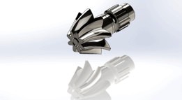
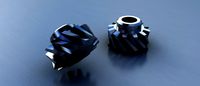
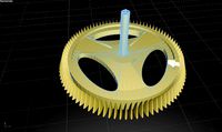
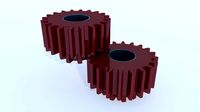
Helical Gear With Motion Study.
Helical or "dry fixed" gears offer a refinement over spur gears. The leading edges of the teeth are not parallel to the axis of rotation, but are set at an angle. Since the gear is curved, this angling makes the tooth shape a segment of a helix. Helical gears can be meshed in parallel or crossed orientations. The former refers to when the shafts are parallel to each other; this is the most common orientation. In the latter, the shafts are non-parallel, and in this configuration the gears are sometimes known as "skew gears".
The angled teeth engage more gradually than do spur gear teeth, causing them to run more smoothly and quietly With parallel helical gears, each pair of teeth first make contact at a single point at one side of the gear wheel; a moving curve of contact then grows gradually across the tooth face to a maximum, then recedes until the teeth break contact at a single point on the opposite side. In spur gears, teeth suddenly meet at a line contact across their entire width, causing stress and noise. Spur gears make a characteristic whine at high speeds. For this reason spur gears are used in low-speed applications and in situations where noise control is not a problem, and helical gears are used in high-speed applications, large power transmission, or where noise abatement is important.
The speed is considered high when the pitch line velocity exceeds 25 m/s.
A disadvantage of helical gears is a resultant thrust along the axis of the gear, which must be accommodated by appropriate thrust bearings, and a greater degree of sliding friction between the meshing teeth, often addressed with additives in the lubricant.
Similar models
grabcad
free

Helical Gear Wheel
... degree of sliding friction between the meshing teeth, often addressed with additives in the lubricant.
likes are appreciated...
grabcad
free

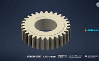
HELICAL GEAR by Pawan Hande
...n. in the latter, the shafts are non-parallel, and in this configuration the gears are sometimes known as "skew gears".
grabcad
free

Helical Gear
...urved, this angling makes the tooth shape a segment of a helix.
helical gears can be meshed in parallel or crossed orientations.
grabcad
free

Helical Gear
...curved, this angling makes the tooth shape a segment of a helix. helical gears can be meshed in parallel or crossed orientations.
grabcad
free

Helical Gear Render
...curved, this angling makes the tooth shape a segment of a helix. helical gears can be meshed in parallel or crossed orientations.
grabcad
free

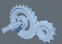
Helical Gear Shaft
...shaft grabcad helical gears are used with parallel shafts similar to spur gears and are cylindrical gears with winding...
grabcad
free

Helical Gear
...helical gear grabcad helical gears are similar to spur gears except that their teeth are cut...
grabcad
free

Helical Gear
...radually extends along the diagonal line across the tooth resulting in smooth engagement and quiet operation even at high speeds!
grabcad
free

Helical gear
...r a refinement over spur gears. the leading edges of the teeth are not parallel to the axis of rotation, but are set at an angle.
grabcad
free

Spur gear
.... no axial thrust is created by the tooth loads. spur gears are excellent at moderate speeds but tend to be noisy at high speeds.
Helical
3d_export
$5
helical gear
...helical gear
3dexport
helical gear
3d_export
$5
Helical Gear
...l contact ratio which can improve vibration and noise. badly designed helical gears can be noisier than well designed spur gears.
turbosquid
$5
Helical Gear
...squid
royalty free 3d model helical gear for download as stl on turbosquid: 3d models for games, architecture, videos. (1502723)
turbosquid
$4

helical gears
...id
royalty free 3d model helical gears for download as blend on turbosquid: 3d models for games, architecture, videos. (1423917)
turbosquid
$40

Helical Stairs
...el helical stairs for download as 3ds, max, ige, obj, and fbx on turbosquid: 3d models for games, architecture, videos. (1422987)
turbosquid
$32

armchair-Helical
... available on turbo squid, the world's leading provider of digital 3d models for visualization, films, television, and games.
turbosquid
$20
helical gear
... available on turbo squid, the world's leading provider of digital 3d models for visualization, films, television, and games.
turbosquid
$10

helical gear
...cal gear for download as max, unitypackage, 3ds, fbx, and obj on turbosquid: 3d models for games, architecture, videos. (1667275)
turbosquid
$4

Helical gear
... gear for download as sldpr, 3dm, 3ds, fbx, ige, obj, and stl on turbosquid: 3d models for games, architecture, videos. (1530622)
3d_export
$50

HELICAL BEVEL GEAR
...lel and perpendicular. in parallel-axis helical gears the two opposite-hand gears provide quiet operation and high load capacity.
Gear
3d_ocean
$4
Gears
...gears
3docean
gear gears iron
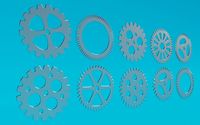
4 different size of gears
3d_export
$5
gear
...gear
3dexport
gear
3d_export
free
Gears
...gears
3dexport
gears
3d_export
$5
gear
...gear
3dexport
a simple model of gear
3d_export
$5
gear
...gear
3dexport
gear for transmission , case machine
3d_ocean
$3
Gears
...nical parts process steampunk vehicle wheel work
10 different gear models volume 01-10 files: .3ds .c4d .obj note: you need vray
3d_ocean
$1

Spur Gear
...spur gear
3docean
decoration gear
a typical spur gear
3d_ocean
$4
Gear wheels
...gear wheels
3docean
engine engineering gear gears industry machinery mechanical toothwheel wheel
pair of gear wheels : animated.
turbosquid
$9
Gear
...gear
turbosquid
royalty free 3d model gear for download as on turbosquid: 3d models for games, architecture, videos. (1712328)
turbosquid
$2
Gears
...rs
turbosquid
royalty free 3d model gears for download as ma on turbosquid: 3d models for games, architecture, videos. (1166710)