Thingiverse
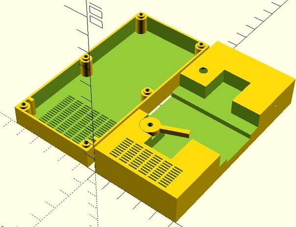
Gumstick Battery Charger Project Case
by Thingiverse
Last crawled date: 4 years, 2 months ago
This is a project box for a DIY gumstick battery charger. The box has the following features:
Slots to accommodate a circuit board
Ventilation for cooling the electronics
Hole to accommodate a 5mm LED
Holes to accommodate a power socket or directly wired power lead
A battery retainer, in case the battery wants to pop out
The negative terminal is made from single core mains conductor, with a diameter of 1.3mm -there is a hole in the side of the box to aid insertion. The wire is kinked such that it can make contact with the battery.
The positive terminal is cut from 0.3mm copper sheet -this is flexible enough to insert from within the box. The gap betweeen the copper terminal and the case is filled with some flexible material, like hot-melt glue. The ends of both terminals are folded around on the inside and soldered together.
The charging circuit is out of the scope of this project, but it can be quite simple like a suitably rated resistor, so long as a timer is used. I used a 2 transistor constant-current charger circuit (see diagram), which is designed to work on an input voltage of 5V and provides an average of around 210mA -this circuit also requires a timer. Transistor Q1 must be able to dissipate 820mW.
Similar models
thingiverse
free

Gumstick Battery charge adapter by greasemonkey089
...ires through the holes (as seen on my photos) and your are able to fit a gumstick battery into a common charger for aa batteries.
thingiverse
free

Project Box with Power Supply by wimberleytech
... be tapped #4-40
added another box replacing toggle switch with rocker switch and bosses are designed for #4-40 threaded inserts.
thingiverse
free

9v battery holder by mlindekugel
...ooves for the terminals, then soldered the wires to the tape; seems to hold well enough, especially once the battery is inserted.
thingiverse
free

Push fit circuit boards by mattvenn
...wires like leds and resistors.
the example file is for a moodlamp, but you can use the openscad file to create your own circuits.
thingiverse
free

ESP8266 Project Box with Battery (18650, charger, On/Off-Button) by Timothy3001
...74665101
i connected the power of the led in the switch via a transistor with the esp so i can control the light programmatically
grabcad
free

Portable Charger Case
... be inserted. the casing has an opening for a standard usb cable to be inserted. this case is designed to fit around an iphone 7.
grabcad
free

Wireless Electricity project
...f-made insulated copper wire coil to achieve wireless power transmission, showcasing the potential for wire-free energy transfer.
thingiverse
free

SMALL POWER SUPPLY CASE by weed2all
...a switch and a normal 3 pin power adapter like you have in the atx power supply, and also a small hole for the 12v wires came out
thingiverse
free

Power tool wireless charger by digdug
...other circuits.
see https://youtu.be/00vh0qvs_gw and http://contest.open-electronics.org/project/wireless-charging-electric-tool/
thingiverse
free

transistor tester case by cbruner
...t. includes screw posts, just use wood screws to hold circuit board down to screw holes. battery fits underneath circuit board.
Gumstick
thingiverse
free
Gumstick Battery charge adapter by greasemonkey089
...ires through the holes (as seen on my photos) and your are able to fit a gumstick battery into a common charger for aa batteries.
thingiverse
free

Gumstick Battery Storage Box by epsilon748
... to cover it. can be printed with whatever filament but i used petg in the photo
printed in .3mm layer draft mode on my prusa mk3
thingiverse
free

Battery holder for gumstick-style (Whoop) packs by MicroMotorWarehouse
...) packs by micromotorwarehouse
thingiverse
holds 8x 150-205mah stick packs, as we use them on the whoop.
ready for consumption..
thingiverse
free

Gumstick Battery Eneloop Charging Adapter by ThisDoesNotCompute
...ome inspiration came from this similar adapter (great minds think alike, and all that): https://www.thingiverse.com/thing:3047798
thingiverse
free

Gumstick Battery Adapter (Sideways Print) by EaziG
...ome inspiration came from this similar adapter (great minds think alike, and all that): https://www.thingiverse.com/thing:3047798
thingiverse
free

Gumstick Case for 4 Batteries by Himeno
...ause i must make thicker under the batterie.
you need 4 magnet from the size 8,00x3,00x2,00mm.
2 for the case and 2 for the cover
thingiverse
free

AA-Gumstick adapter (dual) by amethystjw
... maybe aluminum foil folded into many layers (maybe 20 layers thick and pressed flat with a vice could work; i did not try this).
thingiverse
free

Walkman AAA Battery compartment (ultra compact) by greasemonkey089
...that where designed to run with the so called 'gumstick batteries' where equipped with external battery contacts for screw-on...
Charger
3d_export
$5
charger
...ers in battle. this is the 18th century meaning of charger, and it’s based on the verb charge and its meaning “rush into battle.”
3d_export
free
Charger
...charger
3dexport
turbosquid
$15

Charger
... available on turbo squid, the world's leading provider of digital 3d models for visualization, films, television, and games.
turbosquid
$3

Charger
...d model charger for download as skp, max, blend, stl, and obj on turbosquid: 3d models for games, architecture, videos. (1654816)
turbosquid
$1
charger
... available on turbo squid, the world's leading provider of digital 3d models for visualization, films, television, and games.
3d_export
$20

dodge charger 1972
...dodge charger 1972
3dexport
dodge charger 1972
3d_export
$20
dodge charger 1969
...dodge charger 1969
3dexport
dodge charger 1969
3d_export
free

dodge charger 1969
...dodge charger 1969
3dexport
dodge charger 1969
3d_export
$18

dodge charger
...dodge charger
3dexport
3d_export
$89
Charger 3D Model
...charger 3d model
3dexport
charger sea transopt industry 3d models
charger 3d model vitaly amurskiy 2286 3dexport
Battery
3d_ocean
$2

Battery
...battery
3docean
battery electronic
a high quality battery .
3d_export
free
battery
...battery
3dexport
battery
3d_ocean
$5
Battery
...battery
3docean
battery electronics
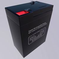
a classic 6 v battery, high poly with materials
3d_ocean
$3
Batteries
...batteries 3docean aa aaa batteries battery d electronics energy materials power subdivision uv unwrapped aa,...
3d_export
$19
Lead-acid battery storage battery lithium battery
...ttery storage battery lithium battery
3dexport
1.lead-acid battery storage battery lithium battery 2.files include 3dmax obj fbx
3d_ocean
$7

Battery Model
...battery model
3docean
big battery car battery vehicle battery
car battery, big battery, vehicle battery.
3ddd
free

battery energier
...battery energier
3ddd
battery energier , батарейка
battery energier
turbosquid
free
battery
...battery
turbosquid
free 3d model battery for download as obj on turbosquid: 3d models for games, architecture, videos. (1151676)
3d_ocean
$1
Battery Model
...lack minus plus white yellow
this is battery model is about 1000 triangles. turntable preview is smoothed version of the battery.
3d_export
$10

battery 18650
...battery 18650
3dexport
battery 18650
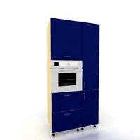
Case
3d_export
$1

case
...case
3dexport
case
archibase_planet
free
Case
...case
archibase planet
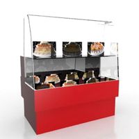
showcase show-case glass case
glass-case + cakes - 3d model for interior 3d visualization.
archibase_planet
free
Case
...case
archibase planet
showcase show-case glass case
glass-case for chips - 3d model for interior 3d visualization.
archibase_planet
free
Case
...case
archibase planet
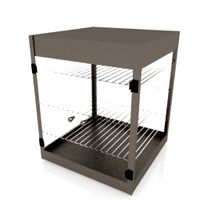
case shelving drawer
case - 3d model for interior 3d visualization.
archibase_planet
free
Case
...case
archibase planet
case rack locker
case - 3d model for interior 3d visualization.
archibase_planet
free
Case
...case
archibase planet
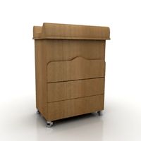
case drawer kitchen furniture
case - 3d model for interior 3d visualization.
archibase_planet
free
Case
...case
archibase planet
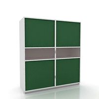
case cupboard shelving
glass case - 3d model for interior 3d visualization.
archibase_planet
free

Case
...case
archibase planet
case handbag suitcase
case - 3d model (*.gsm+*.3ds) for interior 3d visualization.
archibase_planet
free

Case
...case
archibase planet
case suitcase
case 5 - 3d model (*.gsm+*.3ds) for interior 3d visualization.
archibase_planet
free
Case
...case
archibase planet
locker case dresser
case - 3d model (*.gsm+*.3ds) for interior 3d visualization.
Project
3d_export
$7
project
...project
3dexport
project
3d_export
$20
Project
...project
3dexport
design_connected
$16

Project Chair
...project chair
designconnected
rex kralj project chair computer generated 3d model. designed by žitnik, marjan.
3ddd
$1

lectric Project
...настроены. сетка очень плотная.
доступно только для группы "profi"
про группу "profi" можно прочитать в чаво
3d_ocean
$19

Soon project
...kup. made in 3ds max 2013 1- 3dsmax with vray render included material and light 2- obj file 3- fbx file hope you like it plea...
turbosquid
$49

Joint | Project
...squid
royalty free 3d model joint | project for download as on turbosquid: 3d models for games, architecture, videos. (1297983)
turbosquid
$11

house project
...bosquid
royalty free 3d model house project for download as on turbosquid: 3d models for games, architecture, videos. (1672482)
turbosquid
$450

University project
...
royalty free 3d model university project for download as rvt on turbosquid: 3d models for games, architecture, videos. (1463354)
turbosquid
$30
smart projecter
...lty free 3d model smart projecter for download as max and obj on turbosquid: 3d models for games, architecture, videos. (1236214)
3d_export
$5
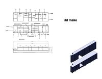
project drawing
...project drawing
3dexport
project drawing and 3d model<br>format jpg sldprt dwg<br>by 3d make