Thingiverse
Grid Clock v2 REMIX - Fully Enclosed Version with Adrunio Nano or NodeMCU options by MyStoopidStuff
by Thingiverse
Last crawled date: 4 years, 5 months ago
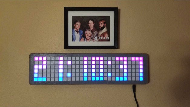
This is a remix of Parallyze's Awesome Grid Clock V2 (https://www.thingiverse.com/thing:3433644), and uses the "GCv2_Grid_Base_v1.stl" and "GCv2_Grid_v1.stl" parts from the original model. All the clock dimensions, aside from thickness are the same as the original design. I recommend that you use the instructions from the original for the basic assembly and electronics design, which will serve you better than anything I could write up for this remix.
The idea behind this remix was originally to make the top part fully printable (no filter paper or screens required), with some surface textures, using a trick in the slicer (Cura) where multiple models can be merged into one, and you can have some of those models print normally and others as supports. I will try and explain how to do this in the print settings section, but the technique allows you to get some interesting top or bottom textures on your prints.
After making the top part separate, I thought, why not just make it fully enclosed? So a simple change spiraled out of control, and now it is fully enclosed, with mounting points for the electronics, an optional fuse holder, LDR holder, and wall mounting holes and wall mounting pegs that can use 3M command strips.
This uses some additional hardware (additional to the hardware needed for the original Grid Clock V2)
M3x10mm screws to hold the back plates on (16 to 24 depending on the size of the clock)
M3x16mm screws (optional - 2 needed for the fuse holder)
M3 x 8mm screw to secure the Arduino Nano (if using that design).
M3 locknuts (optional - 2 needed for the fuse holder)
DC panel jack (looks similar to ama-zon Item B077YB75N3 - see note below)
Standard Auto Fuse if using the fuse holder option
LDR (I used one I had around - the hole for the LDR is about 7.6mm dia)
(note about the DC jack connectors - the 5.5mm jacks come in two sizes (5.5x2.1mm and 5.5x2.5mm), so it would be best to find out what jack your power supply will use and just get that type. Most of mine are 5.5x2.1mm jacks. The hole for the DC jack is 11.98mm in diameter and has flats on the top and bottom)
If you are using a DS3231 RTC module and will power it with 5V please see the note below in the post-printing section, and this link for an important safety consideration:(Thanks again to Parallyze for point that out to me!)
https://www.onetransistor.eu/2019/07/zs042-ds3231-battery-charging-circuit.html
Thanks and acknowledgements:
Parallyze for the Grid Clock V2 design and code this is remixed from, as well as his support for some of my questions regarding the code. This design is based off his model and uses his code.(BIG THANKS!):https://www.thingiverse.com/thing:3433644
The Arduino Nano mount is remixed from AlpoHassinen's Arduino Nano Holder:https://www.thingiverse.com/thing:2635159
The fuse holder will require the parts from Erik Cederberg's design posted on Thingiverse by sk8rjesshttps://www.thingiverse.com/thing:1787609https://www.youmagine.com/designs/stackable-fuseholder
Print List:
For a SMALL clock:
Print 2 each of these:
Clock_Remix-NEW-7J-SIDE-CLIP-TOP.stl
Clock_Remix-NEW-7J-SIDE-CLIP-BOTTOM.stl
Clock_Remix-NEW-7F-BU-BUTTON-CLIP.stl
Clock_Remix-NEW-7G-BU-COMMAND-STRIP-WALL-MOUNT.stl (optional)
You will also need 2 "RL-TOP"s which are composed of the following (see printing notes below for these):
Clock_Remix-NEW-6S-RL-TOP-GRID.stl
Clock_Remix-NEW-6S-RL-TOP-SCREEN-BASE.stl
Clock_Remix-NEW-6S-RL-TOP-SCREEN-TEXTURE.stl
Clock_Remix-NEW-6S-RL-TOP-INSERTS-SUPPORT.stl
These will need to be downloaded from the orginal design and printed (2 are needed)
"GCv2_Grid_Base_v1.stl" and "GCv2_Grid_v1.stl"
Print one of these:
Clock_Remix-NEW-7K-R-BASE-TRONICS-ARDUNIO-NANO.stl
-or-
Clock_Remix-NEW-7K-R-BASE-TRONICS-NODE-MCU.stl
Clock_Remix-NEW-6S-M-BASE-NO-WALLHOOK.stl
-or-
Clock_Remix-NEW-6S-M-BASE-WALLHOOK.stl
Clock_Remix-NEW-6S-L-BASE.stl
Clock_Remix-NEW-7K-R-SIDE-SHELL.stl
Clock_Remix-NEW-7K-L-SIDE-SHELL.stl
For a LARGE clock:
Print everything listed above. Additionally, print one of each of the following:
This will need to be downloaded from the orginal design and printed (1 more is needed):
"GCv2_Grid_Base_v1.stl" and "GCv2_Grid_v1.stl"
The rest of the parts are here:
Clock_Remix-NEW-6S-M-BASE-NO-WALLHOOK.stl
-or-
Clock_Remix-NEW-6S-M-BASE-WALLHOOK.stl
Clock_Remix-NEW-7K-M-SIDE-SHELL.stl
You will also need an additional "M-TOP" which are composed of the following (see printing notes below for these):
Clock_Remix-NEW-6S-M-TOP-GRID.stl
Clock_Remix-NEW-6S-M-TOP-SCREEN-BASE.stl
Clock_Remix-NEW-6S-M-TOP-SCREEN-TEXTURE.stl
Clock_Remix-NEW-6S-M-TOP-INSERTS-SUPPORT.stl
The STEP files are included for easy remixing. If you have feedback on this remix, please post it and I will try to assist with questions.