Thingiverse
Greg's Beefed'wadestruder B'struder Remix Geared Bowden Extruder by ggroloff
by Thingiverse
Last crawled date: 4 years, 4 months ago
This is a beefed up version of Greg's B'Wadestruder - Geared B'struder by VanessaE.
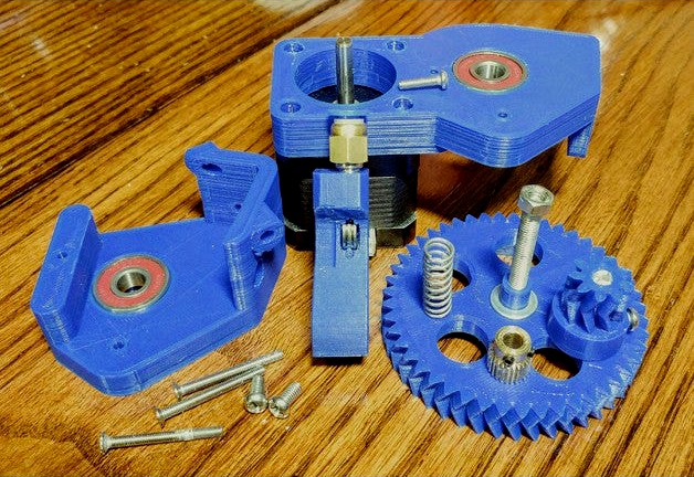
This works with the stock anet a8 extruder stepper, hobbed gear and idler bearing. It should work with others too, that is just what I have. This is a bowden extruder so you will need to buy some M6 ptfe tube fittings and ptfe tube. You'll also need to buy a 45 mm M5 bolt and some 608 bearings (or try printed or out of an old fidget spinner). All other screws I needed to use already had extras from the Anet A8.
See it in action:https://youtu.be/OLfVsnN3ViY
Update 10/2/18: Changes to top plate: Increased thickness of top plate to 10 mm - same as bottom plate for symmetry. Increased depth of top plate bearing slot. Narrowed idler arm enclosure by 0.5 mm. Tightened motor brace tolerance by .1 mm. Completely happy with the top plate for now. Updated pictures.
Changes to base plate: Moved set screw access down by 1.5 mm. Wasn't a big problem before but now it's closer to the set screw position once assembled.
Added idler arm guide bushing. This should make it easier to align the hinge with the arm once the top plate is on. Use is optional, it goes on the side of the idler arm which faces the top plate.
End of updates.
I noticed my original Greg's B'Wadestruder base plate was flexing when using high retraction speeds (>35 mm/s). I was also unhappy with the play between my m5 screw and the ID of my 625zz bearing, making the gear a bit off. I also noticed the hinge for my B'struder's idler arm was flexing back and forth a bit during these retractions, slowly getting weaker.
So on to the changes:
-Now uses 608zz bearings for the top and bottom plate; you can print a spacer to bring the tolerance to the m5 axle really tight. Also more widely available, and has 3d printable versions as this is a low speed application. Opens the possibility to upgrade to a geared extruder without purchasing any bearings.
-Base plate is now 3 mm thicker, and the holes and all nut slots have been removed. Nuts cost money and they don't need to be there.
-Base plate now mounts flush to the edge of the motor. (Can now stand upright with a flat surface)
-Top plate is now 3 mm thicker
-Top plate now supports the hinge for the idler arm. Hinge now supported from both sides. The hinge now uses a 30 mm m3 screw.
-Top plate now braces against the motor and is connected to the base plate on both sides of the idler arm with an extra 30 mm m3 screw.
-Nut has been removed from the idler arm, replaced with countersink for idler pulley screw. This slims the idler arm enclosure, and a nut isn't needed here as there is no stripping force during operation. Now uses 10 - 12mm screws, m3 for 623zz and m4 for Anet A8 u-groove bearing.
-Set screw access on base plate moved to make the base stronger.
Additional info:
Same 5.222 to 1 ratio. You'll have to reflash the firmware to run the stepper backwards and re-calibrate the extruder stepping (e-steps). I'm running TH3D firmware, so I enabled the titan geared extruder setting in the configuration.h to run the stepper backwards, and my e-steps value here ended up coming to exactly 500 for my stock anet a8 hobbed gear and stepper. This may vary for you depending on your firmware, motor and hobbed gear. This e-step value was determined by sending g-code to extrude 100 mm of filament (disconnected from the hot end), and adjusting the value until exactly 100 mm of filament was fed.
I printed the arm at 100% infill, and the base and top at 50% with 1.2 mm walls. Supports for all.
Idler arms are for the original 623zz bearing as well as for the Anet A8 13mm u-groove bearing. Threw in some bushings you can use for the hinge instead of bearings also.
Included the original gear .stls for ease.
A neat trick I discovered is to use a long m3 screw for the spring mount, that way you can screw it far down until it touches the idler arm. This locks the arm in position against the axle.
If your m5 screw head is a tiny bit too small for the gear as there can be variances in screw heads, you can lay a sheet of tinfoil and poke the screw threads through it (like a big 1 layer tinfoil washer), then feed that through the gear - the tinfoil will crush and fill up the space around the hex head. Same principle for the drive gear and the stepper shaft.
Since then I've been able to run retractions at 60 mm/s (haven't gone higher yet) and not see any flexing in the base plate or the arm.
You can use a m5 washer as a spacer to lift the gear away from the bearing/base plate.
**Pictures are now up to date