Thingiverse
Glass Bed Lighting by DGDG5
by Thingiverse
Last crawled date: 4 years, 7 months ago
Description
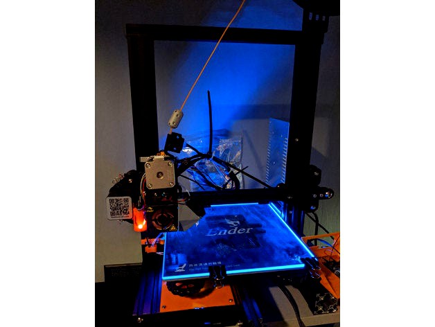
This project adds rgb lighting to your 3D Printer. The stl files provided are specifically designed for the Creality Ender 3 with BLTouch installed. Feel free to remix this to make a fitting variant for your printer model, but take note of the license first.
Why should i need this?
Makes first layers perfectly visible
Shows dust particles on bed and all small cracks/scratches
Shows any dirt/fat/fingerprints on the bed
Hardware used
Necessary
1 piece: PCB for SMD led's - 0402/0603/0805
4 pieces: RGB led's 3528 (common anode/VCC)
2 pieces: M4x10
1 piece: 12 Ohm resistor
X pieces: 30 AWG Wires
1 piece: Borosilicate glass, transparent with milky edges
1 piece: Raspberry Pi (any model)
Optional
Dupont DIY kit
Heat shrink tubes
Cable clip
PTC heating plate (to solder the led's on the pcb)
It's best to buy these parts from aliexpress if you have patience, so you don't have to sell a kidney to be able to afford them from amazon. By now they offer a 10-day delivery for a lot of products.
Software Used
OctoPrint
OctoPrint-Enclosure (Plugin)
Assembly
Print the provided stl files, support needed for the pcb holder
File down the printed parts if necessary, so the mechanism works seamlessly
Solder the rgb led's to the pcb
Solder wires to the other side of the pcb
Slide the pcb into the housing
Solder the wires together by bundling each color to a single wire. Same for VCC/anode
Place the bottom part on your printer and put the two M4x10 screws in
Slide the assembled top part containing the pcb into the frame first, then slide it down and into the broad hole, the bottom part provides
Add a 12 Ohm resistor to the red LED's wire. Red is rated ~2.2V DC, Blue and Green ~3.3V DC each
Connect the wires to your Raspberry Pi. VCC goes to a constant 3.3V pin. The rest of the wires to a gpio pin each
Software setup
Install the OctoPrint-Enclosure Plugin, linked above
Go to your plugin settings and assign the corresponding GPIO pin of each color to an output for each. E.g. Red led is connected to GPIO 5, so its output type is "Regular IO", its id is 1 (automatically assigned), its "IO number" is 5 and "Active Low" is checked
Control
Via button: Click on "Enclosure Plugin" tab in your OctoPrint Web-Interface to either turn on or off each color
Via gcode: In the plugin settings of enclosure plugin, scroll to the bottom, open the advanced settings and check "Enable gcode control" to be able to control your lights using G-Codes. This gives you the ability, to e.g. turn the bed red when a print job starts and green once the print is finished. Read the docs. An example:
ENC O1 S0 ; Red bed light off
ENC O2 S1 ; Green bed light on
ENC O3 S0 ; Blue bed light off
Notes
The led's used have a common anode, not the best solution. i used what i had. Instead, using WS2812 (neopixels) would be a lot cleaner, but i am missing a controller IC and don't want to add an arduino just for that. This would however decrease the cable count to be wired to the PCB.
The GPIO pins serve as ground pins, so setting a color's pin to low would turn the light on and vice versa. If you decide to use PWM instead (which would enable you to control the brightness), a duty cycle of 0 would turn on the light, 100 turns it off.
On an Ender 3, the max Y-axis coordinate that is lightable is Y=170. Anything higher than that is not reachable by the led bar and would go dark.
I highly recommend you to get the "optional" PTC heating element to solder on the led's. I initially tried to to it with my soldering iron, terrible results, even with enough flux. Then with a heat gun, also bad. The PTC heating plate turned this into a childs play, the led's just snapped into their places (pre-tin the upper face first and use flux)
Disclaimer
I am not responsible for any damage you might cause, execute this build at your own risk.