Thingiverse
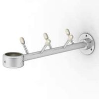
GeeeTech LCD bracket for Printrbot Play by TychoSchenkeveld
by Thingiverse
Last crawled date: 3 years ago
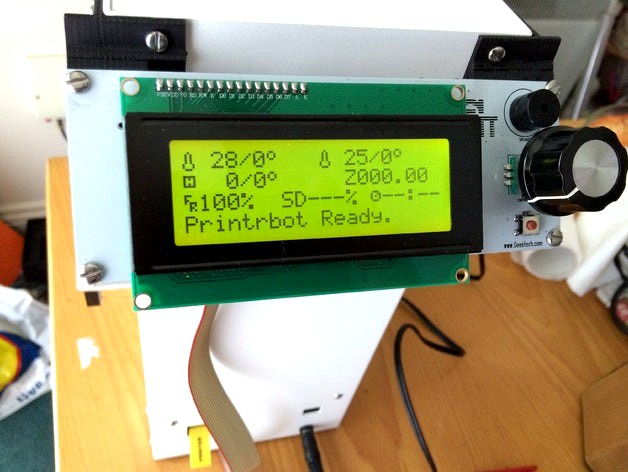
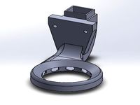
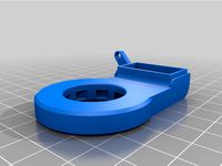
Bracket for a cheap (Chinese) Geeetech Ramps 1.4 LCD controller to mount it on the Printrbot Play (http://www.geeetech.com/reprap-ramps-v14-smart-2004-lcd-controller-with-adapter-p-615.html)
Please note there is also an official Printrbot LCD controller which will no doubt fit better. But printrbot's shipping is so expensive to Europe so it was a bit cost-prohibitive. And it looks like it's out of stock at the moment.
I mounted it on the right-hand side panel because it's easy to route the cable from there (the printrboard is at the bottom of this panel). I usually have it on a table so the 45 degree angle gives me a good view of the LCD. I briefly considered putting it at the front below the print bed but the bed would obstruct the view when it moved. This way isn't really ideal either because the controller is wider than the printrbot play is deep, but it does the job and the existing screwholes make for easy and solid mounting.
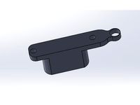
The support on the right-hand side is bigger to provide enough support for pressing on the rotary controller. Also, the left-hand side has a lot more sticking out at the back so I couldn't do the same there.
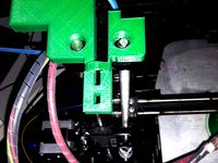
This prints fine on the printrbot play. Mount it with 4 M3 bolts - you'll need longer ones than the ones provided with the printer so you will need to replace the factory ones. I used 10mm long ones, they were slightly too long (but don't cause a problem).
The display itself I mounted with the same bolts and 4 nylon M3 locknuts. Holes in the brackets are big enough to fit.
I did get some warping on this design (even though it was printed in PLA), I don't have the optional heatbed so that's probably why. There's some stress on the controller board due to this but it doesn't seem to cause a problem.
You WILL need to make a custom cable for this! Here's how to wire it.
Printrboard EXP2 Side LCD Side
--------------------- --------
Pin 1 (GND) EXP1 - Pin 9
Pin 2 (5V) EXP1 - Pin 10
Pin 3 - Not Connected -
Pin 4 - Not Connected -
Pin 5 (D7) EXP1 - Pin 8
Pin 6 (D6) EXP1 - Pin 7
Pin 7 (D5) EXP1 - Pin 6
Pin 8 (D4) EXP1 - Pin 5
Pin 9 - Not Connected -
Pin 10 (E) EXP1 - Pin 3
Pin 11 (RS) EXP1 - Pin 4
Pin 12 (ROT_A) EXP2 - Pin 5
Pin 13 (ROT_B) EXP2 - Pin 3
Pin 14 (ROT_SW) EXP1 - Pin 2
Some people have done this with a custom board - I just wired the wires accordingly to IDC connectors and crimped them. No active parts or splits needed so why bother with more.
The SD card reader on the LCD controller doesn't work, but it doesn't matter as you can use the microSD slot on the printrbot itself. Nor does the buzzer (at least I've never heard it do anything).
Enjoy and just send me a message here if you have any problems.
PS Make sure you rotate them on their side with the little side tab lowest to the bed, that way you will only need support for the side tab for approx. 1cm which is not a lot. Printed fine like that here.
There's a few little flaws in it, some tiny strip gaps that didn't quite match up but because they're so close they link up fine anyway in the actual print. This is because 123D Design doesn't allow sketches to snap together if they're in different planes (or at least I haven't figured out how to do that yet!). But it worked fine like this and suited the purpose so I left it like this.
Took about 2x 1 hour to print. Gap left for the SD card reader on the back (slightly too large because on my first go around it was slightly too narrow so I overdid it a bit as I didn't want to waste another hour's print time :) ).
Please note there is also an official Printrbot LCD controller which will no doubt fit better. But printrbot's shipping is so expensive to Europe so it was a bit cost-prohibitive. And it looks like it's out of stock at the moment.
I mounted it on the right-hand side panel because it's easy to route the cable from there (the printrboard is at the bottom of this panel). I usually have it on a table so the 45 degree angle gives me a good view of the LCD. I briefly considered putting it at the front below the print bed but the bed would obstruct the view when it moved. This way isn't really ideal either because the controller is wider than the printrbot play is deep, but it does the job and the existing screwholes make for easy and solid mounting.
The support on the right-hand side is bigger to provide enough support for pressing on the rotary controller. Also, the left-hand side has a lot more sticking out at the back so I couldn't do the same there.
This prints fine on the printrbot play. Mount it with 4 M3 bolts - you'll need longer ones than the ones provided with the printer so you will need to replace the factory ones. I used 10mm long ones, they were slightly too long (but don't cause a problem).
The display itself I mounted with the same bolts and 4 nylon M3 locknuts. Holes in the brackets are big enough to fit.
I did get some warping on this design (even though it was printed in PLA), I don't have the optional heatbed so that's probably why. There's some stress on the controller board due to this but it doesn't seem to cause a problem.
You WILL need to make a custom cable for this! Here's how to wire it.
Printrboard EXP2 Side LCD Side
--------------------- --------
Pin 1 (GND) EXP1 - Pin 9
Pin 2 (5V) EXP1 - Pin 10
Pin 3 - Not Connected -
Pin 4 - Not Connected -
Pin 5 (D7) EXP1 - Pin 8
Pin 6 (D6) EXP1 - Pin 7
Pin 7 (D5) EXP1 - Pin 6
Pin 8 (D4) EXP1 - Pin 5
Pin 9 - Not Connected -
Pin 10 (E) EXP1 - Pin 3
Pin 11 (RS) EXP1 - Pin 4
Pin 12 (ROT_A) EXP2 - Pin 5
Pin 13 (ROT_B) EXP2 - Pin 3
Pin 14 (ROT_SW) EXP1 - Pin 2
Some people have done this with a custom board - I just wired the wires accordingly to IDC connectors and crimped them. No active parts or splits needed so why bother with more.
The SD card reader on the LCD controller doesn't work, but it doesn't matter as you can use the microSD slot on the printrbot itself. Nor does the buzzer (at least I've never heard it do anything).
Enjoy and just send me a message here if you have any problems.
PS Make sure you rotate them on their side with the little side tab lowest to the bed, that way you will only need support for the side tab for approx. 1cm which is not a lot. Printed fine like that here.
There's a few little flaws in it, some tiny strip gaps that didn't quite match up but because they're so close they link up fine anyway in the actual print. This is because 123D Design doesn't allow sketches to snap together if they're in different planes (or at least I haven't figured out how to do that yet!). But it worked fine like this and suited the purpose so I left it like this.
Took about 2x 1 hour to print. Gap left for the SD card reader on the back (slightly too large because on my first go around it was slightly too narrow so I overdid it a bit as I didn't want to waste another hour's print time :) ).
Similar models
thingiverse
free

Printrbot Printrboard mounting bracket by milstrata
...things/dy7r20xrkj6
this is a bracket to mount a printrboard (printrbot electronics board) to one of the printrbot's z motors.
thingiverse
free

Ramps 1.4 with Anet display and external SD card reader by stefankck
...:4
exp2:4 - sd:cs
exp2:5 - lcd:6
exp2:6 - sd:det (7th pin on socket)
exp2:7 - sd:mosi
exp2:8 - j3:7
exp2:9 -
exp2:10 -
thingiverse
free

Printrbot Play LCD Bracket & PI by lukewin8
...gled.
pi bracket
print and use 4x 5mm stand offs and 4x 8mm (m3)
plus some stick pads
http://lukeredler.wix.com/led-projects
thingiverse
free

Printrbot Simple Ribbon Cable Brackets by drewsloan
...th a ribbon cable. no more taking apart the wire bundle to find the break. if the ribbon cable wears out, just plug in a new one.
thingiverse
free

Print Rite Display Box by bgsteveg
...ronics box, so no extra holes are needed in the original case.
needed a slightly longer cable than what came with the controller.
thingiverse
free

Viki LCD Tripod mount (US) and MakerGear M2 Side Bracket by designrama
... doesn't have the middle metal rod, but don't worry about it because foam tape will hold the handlebar in place securely.
thingiverse
free

LCD Screen Mount for Printrbot Play by papajohnfuller
...ion on how to install an lcd screen please check out my the following link:
https://www.youtube.com/watch?v=ikmpzxqohw4&t=10s
thingiverse
free

NexStar Evolution Bracket by tgmorris99
...e hand control slips into place.
created using tinkercad
printed using 40% infill but probably doesn't need to be that dense.
thingiverse
free

Prusa i3 mk3 LCD pannel side mount brackets by BlueTable
...;ve had no vibration issue with the new brackets.
the lcd pannel doesn't touch the ground, as with the original front mounts.
thingiverse
free

Printrbot Simple metal feet and lcd mount by kevinh6825
...n your slicer so you don't print the clips.
the lcd brackets and cover are remixed from prusa i3 mk3
the feet are my design
Tychoschenkeveld
thingiverse
free

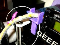
Anti-snag cable guide for Printrbot Play by TychoSchenkeveld
...on here in case anyone else has the same problem (maybe not all printers do)
this is an unapproved mod so try at your own risk!
thingiverse
free

OLED bezel for Maplin PSU box by TychoSchenkeveld
...ok like this but it could fit a little bit better. didn't get a chance to update the design though, will upload here if i do.
Geeetech
3d_export
free
part right for geeetech acrylic i 3
...part right for geeetech acrylic i 3
3dexport
the engine can be shifted
3d_export
free
cable holder
...cable holder 3dexport for geeetech acrylic i...
thingiverse
free
geeetech a10 by Igor_garbuz
...geeetech a10 by igor_garbuz
thingiverse
model geeetech a10 ( solidworks).
thingiverse
free
geeetech calibration by muffler1979
...geeetech calibration by muffler1979
thingiverse
just a calibration test for the bed on a geeetech
thingiverse
free
Fan for Geeetech proB
...fan for geeetech prob
thingiverse
this is my fan for the geeetech pro b i3.
thingiverse
free

Chain for Geeetech A30
...chain for geeetech a30
thingiverse
this is my personal review of chain for geeetech a30.
thingiverse
free
Zugentlastung Hotend Geeetech A30T / Strain relief Geeetech A30T by 3DDennis1983
...zugentlastung hotend geeetech a30t / strain relief geeetech a30t by 3ddennis1983
thingiverse
zugentlastung hotend geeetech a30t
thingiverse
free
Kettenhalter i3x geeetech by Autark
...kettenhalter i3x geeetech by autark
thingiverse
geeetech i3x
thingiverse
free
Geeetech A10 Fanduct by stefan177gr
...geeetech a10 fanduct by stefan177gr
thingiverse
fanduct for geeetech a10
thingiverse
free
Geeetech filament guide by RicardoZ2018
...geeetech filament guide by ricardoz2018
thingiverse
desing for geeetech i3x
Printrbot
thingiverse
free

printrbot gasket by Usernameunavailible
...printrbot gasket by usernameunavailible
thingiverse
a part for printrbots
thingiverse
free

Printrbot Aluminum by Chris_the_Carpenter
...printrbot aluminum by chris_the_carpenter
thingiverse
a redesign of the awesome printrbot, in aluminum.
thingiverse
free

PrintrBot keychain by SuperMaku
...printrbot keychain by supermaku
thingiverse
printrbot keychain. may need to be scaled up.
thingiverse
free

Printrbot foot by aliekens
...printrbot foot by aliekens
thingiverse
add wider feet to a printrbot for improved stability.
thingiverse
free

Printrbot to CNC by mmrrsiam
...printrbot to cnc by mmrrsiam
thingiverse
make your printrbot also a small cnc machine....
thingiverse
free

Printrbot Keychain by jackbivona
...printrbot keychain by jackbivona
thingiverse
printrbot keychain for all you pb customers out there
thingiverse
free

Printrbot+ Nutkeepr by DonaldJ
...printrbot+ nutkeepr by donaldj
thingiverse
clip to retain nut on z-axis threaded rod of printrbot+
thingiverse
free

PrintrBot Tool Caddy by spr_consulting
...printrbot tool caddy by spr_consulting
thingiverse
printrbot tool caddy.
thingiverse
free

Printrbot Sensor Wrench by spr_consulting
...printrbot sensor wrench by spr_consulting
thingiverse
curvaceous printrbot sensor wrench.
thingiverse
free

Spool Holder for Printrbot by doubleAdoubleU
...spool holder for printrbot by doubleadoubleu
thingiverse
spool holder for a printrbot simple metal
Lcd
turbosquid
$20
lcd
... available on turbo squid, the world's leading provider of digital 3d models for visualization, films, television, and games.
turbosquid
$15
LCD
... available on turbo squid, the world's leading provider of digital 3d models for visualization, films, television, and games.
turbosquid
$10
LCD
... available on turbo squid, the world's leading provider of digital 3d models for visualization, films, television, and games.
turbosquid
$10

LCD
... available on turbo squid, the world's leading provider of digital 3d models for visualization, films, television, and games.
turbosquid
$2
lcd
... available on turbo squid, the world's leading provider of digital 3d models for visualization, films, television, and games.
turbosquid
$1
lcd
... available on turbo squid, the world's leading provider of digital 3d models for visualization, films, television, and games.
turbosquid
free
lcd
... available on turbo squid, the world's leading provider of digital 3d models for visualization, films, television, and games.
turbosquid
free

LCD
... available on turbo squid, the world's leading provider of digital 3d models for visualization, films, television, and games.
3ddd
$1
Noti Lcd Sofa
...noti lcd sofa
3ddd
noti , lcd
3d model of noti lcd sofa
3d_ocean
$7

Lcd tube wall
...hrome electronic electronic lcd tv videowall
lcd tube wall you can put in the lcd your own texture or movie in it and animate it.
Play
3ddd
$1
play center
...play center
3ddd
площадка
play center
3ddd
free
Mecplast play
...mecplast play
3ddd
mecplast , play , кресло
archive3d
free
Play 3D Model
...ine playing machine game machine
play n210909 - 3d model (*.3ds) for interior 3d visualization.
archive3d
free

Play 3D Model
...ame-playing machine game machine
play 6 - 3d model (*.gsm+*.3ds) for interior 3d visualization.
3ddd
$1

Dedon play
...p://www.dedon.de/en/collections/detail/collection/play-with-dedon-143/sidechair-1146/play-64.html#armchair-2059/play-64
3d_export
$5
Kitchen knife for play
...kitchen knife for play
3dexport
kitchen knife for play
design_connected
$18

Lazy PLAI
...lazy plai
designconnected
b & b italia lazy plai lounge chairs computer generated 3d model. designed by patricia urquiola.
turbosquid
$1
playing cards
...quid
royalty free 3d model playing cards for download as max on turbosquid: 3d models for games, architecture, videos. (1614013)
3ddd
$1

пластилин Play-Doh
...пластилин play-doh
3ddd
пластилин
пластилин play-doh
archive3d
free

Play 3D Model
...l
archive3d
child's play toy
play n121009 - 3d model (*.3ds) for interior 3d visualization.
Bracket
archibase_planet
free
Bracket
...bracket
archibase planet
bracket corbel holder
bracket 1 - 3d model (*.gsm+*.3ds) for interior 3d visualization.
archibase_planet
free
Bracket
...bracket
archibase planet
bracket corbel console
bracket 5 - 3d model (*.gsm+*.3ds) for interior 3d visualization.
archibase_planet
free
Bracket
...bracket
archibase planet
corbel holder bracket
bracket 6 - 3d model (*.gsm+*.3ds) for interior 3d visualization.
archibase_planet
free
Bracket
...bracket
archibase planet
bracket corbel console
bracket 8 - 3d model (*.gsm+*.3ds) for interior 3d visualization.
archibase_planet
free

Bracket
...bracket
archibase planet
bracket corbel holder
bracket n280911 - 3d model (*.gsm+*.3ds) for interior 3d visualization.
archibase_planet
free
Bracket
...bracket
archibase planet
holder corbel bracket
bracket 9 - 3d model (*.gsm+*.3ds) for interior 3d visualization.
archibase_planet
free
Bracket
...bracket
archibase planet
corbel holder bracket
bracket 10 - 3d model (*.gsm+*.3ds) for interior 3d visualization.
archibase_planet
free
Bracket
...bracket
archibase planet
corbel console bracket
bracket 11 - 3d model (*.gsm+*.3ds) for interior 3d visualization.
archibase_planet
free
Bracket
...bracket
archibase planet
holder console bracket
bracket 12 - 3d model (*.gsm+*.3ds) for interior 3d visualization.
archibase_planet
free
Bracket
...bracket
archibase planet
bracket corbel holder
bracket 13 - 3d model (*.gsm+*.3ds) for interior 3d visualization.