GrabCAD
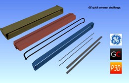
GE Quick Connect and Seal V1
by GrabCAD
Last crawled date: 1 year, 12 months ago
Proposed to use 2 established machine design techniques but adapt them to suit the rectangular configuration of this problem.
1; O-Ring and Dovetail grove system.
2; Internal Circlip technique.
Both of these have been used on circular shafts for very high pressure hydraulic applications in industry.
They have an advantage of both being self retained once assembled and get progressively better when put under pressure.
.
1; Seal Ring (O-Ring) - the BLACK item in model images.
The O-Ring has been guided to swing in a larger radius as it approaches the edge of the rectangular block, it then falls over this curved edge at an angle that causes the seal to travel forward and turn downwards. It mirrors this sequence to come back under the block.
According to the manufacturers guidelines using the dovetail groove recommended tolerances, this seal will perform far in excess of the challenge specification if the cavity housing does not distort under the 3 bar pressure.
The seal will also deliver -1bar vacuum.
I will scan and upload the data sheets later.
.
2; Retaining Clip - The WHITE item in the last model image.
The clip is made to retain the block by being inserted into a groove in the Cavity housing. The face of this groove is angled to cause the block to tighten the clip as pressure increases.
This clip will be in two halves and inserted from the front.
As the clip is distributing the force caused by the pressure build up across the total cross sectional area of the cavity housing, total failure of the housing would have to occur for the block to disengage. (The material for the clip can be chosen to withstand the shearing force across the clips full length, for example it could be metal!!)
To complete this calculation for the maximum force, the data for the material used in the cavity needs to be inputed but it would seem at first glance to be extremely high, far in excess of 3 bar on the blocks surface.
This fixture is removable if required.
.
********* This is a work in progress ************
.
To do.
a; Submit the relevant data sheets.
b; Obtain data for the materials used in the cavity housing.
c; Install a spring stop to position the block (brick) at the required location. This will probably be a rubber strip to allow the clip to engage with the groove.
d;Split the block along the Dovetail to allow moulding in two parts.
These will be glued together before inserting the seal.
e; etc.....
*************** Updated 24thFeb ***********************
a, Data sheets and handbook for the O-Ring selection added.
.
The O-Ring needs to be of a large enough cross section ( as large as possible) to seal against the cavity which will not be perfectly flat.
O-ring cross sections have a minimum bend radius so it cannot just be wrapped around a corner of the block.
The seal would kink at the sharp bend and leak.
This is why the O-Ring is curved in a larger radius as it travels over the corners, it allows the seal to be compressed againts the face of the groove.
.
The O-Ring and grove has been selected to compensate for high volume production molding which will have shrinkage, warping and distortion. For lower pressures, proper sealing can be safely maintained with lower Durometer hardness of the ring material.
.
A softer 70 shore A material is shown in attached graph but as low as 50/60 Shore A could be selected and the tolerance for a larger clearance could be achieved.
.
At the limits of extrusion show in the graph, with total clearance of 0.8mm, a pressure over 6 bar can be sustained.
.
Note; As a stl file of the model has been uploaded, if GE have access to a large bed 3D printer this assembly could be pressure tested. The O-Ring needed is a 3/16"- 0.210" (5.334mm) cross section with a circumerferance of 1084mm. This can be made from a regular O-Ring maintenance kit. For fixing the block can be clamped in position for the test. (Internal circlip details to follow).
.
b.Data obtained for the cavity material from GE.
.
c.Spring stop (spacer pieces) added to locate the block accurately. A square rubber strip is attached (glued) to the back of the block.
.
d.The V-Groove portion of the block has been split for cavity molding with draft angles of 1 degree applied to all sides of the cavity, the block and the groove piece.
These draft angles have been incorporated into a wedge installation for the block into the cavity.
This wedge closes the clearance for the O-ring and minimises (corrects) the effect of warping of the cavity.
.
No post molding machining of the parts is needed at this stage.
Glueing of the groove piece and spacer strips onto the block is the only assembly requirement.
An internal fillet has been added to the cavity to strengthen the area affected by the water pressure, reduce stress concentration and stiffen the chamber where the wedge of the block engages.
.
To do,
e; Add an assembly method for the internal circlip groove.
f; Add technical background information.
.
*******************Updated 27 Feb*****************************
.
e; Added an assembly circlip retaining clip to the front of the cavity.
This clip is glued to a recess in the cavity and acts to secure the block when the circlips are inserted.
The retaining clip will spring on the draft angle of the cavity wall holding it securely while the adhesive is curing. This is a recommended design method from the adhesive manufacturers.
It provides a large overlap area for the adhesive to attach to and keeps the thickness to a minimum. Adhesives are stronger if the thickness in the shear direction is minimised.(refer to the adhesive guidlines uploaded to the folder)
The clip also strengthens the cavity wall from bowing outwards when under pressure.
.
As the retaining clip has a sprung curved edge, the previously proposed rubber spacers where removed at the back of the block. This area is now used to provide support to the pressure chamber at the back by having a sloped engagement with the cavity housing.
.
The internal circlips (internal clips) are formed in a pattern to engage with the retaining clip and can be removed easily by inserting a screwdriver into one of the visible openings at the front.
.
The weakest structural point under pressure would appear to be the adhesive joint between the retaining clip and the cavity.
The clips and retainers are made from stainless steel.
I would recommend that the adhesive engineers are approached to select the bonding agent and they will also recommed the best method of calculating the maximum force. (Refer to their guideline)
.
The finished 3D model is uploaded as Rev 05.
.
I have spent the last 15 years as a piping designer in the BioPharma and Pharmaceutical industries, before that I designed for the manufacturing and electronic sector. Have been using 3D software for machine design since 1990.
If this design concept was acceptable, In my experience it would be best practice if GE could get specialists from the Molding, O-Ring, Adhesive and Spring steel companies on a conference call and coordinate the detail design. These specialists can contribute a level of detail that the designer cannot, but it takes the designer to imagine the concept and co-ordinate these specialists.Sample companies information attached.
A 3D printed sample would help in planning a manufacturing workstation layout.
I estimate that if properly presented to an operator, this assembly could be completed in minutes with only the cure time of the adhesive left to determine the total time to finish.
.
This finished unit cannot be dis-assembled.
An interesting challange, good luck to everyone taking part.
Similar models
grabcad
free

GE Quick Connect and Seal V2
...umes.
the design adheres to overall dimensions specified and this assembly can be dismantled if required by un-hooking the clips.
grabcad
free

FLEXIBLE BEAM SEAL CLAMP FOR GE CONNECTOR
... the brick flange is revised to accept a standard o-ring elastomer seal between the cavity interior and the brick flange o-ring.
grabcad
free

GE Quick Connect V1
...s.
rotate both hinges down in opposite direction.
remove hinges of the assembly.
repeat operation for last three pairs of hinges.
grabcad
free

FLEXIBLE BEAM SEAL CLAMP FOR GE CONNECTOR (Renderings added<, otherwise the same as an earlier entry)
... the brick flange is revised to accept a standard o-ring elastomer seal between the cavity interior and the brick flange o-ring.
grabcad
free

GE Quick Connect Challege
...nd clips perform the retaining function. cap features could be incorporated into the brick which would eliminate the extra part.
grabcad
free

GE quick-connect (flexible design)
...nd can bear 5 bar . pressure)
grabcad
free

Internal Clip and Seal
...internal clip and seal
grabcad
an inverted hairpin clip and retainer press against lower seal and shoulder of insert and brick
grabcad
free

GE Quick Connect
...may be beneficial as reusing cavity may weaken snaps and cause future failures. so in conclusion the cavity would be sacrificial.
grabcad
free

Mold design for plastic knob
...rabcad
this is a mold design for plastic knob , it only consist of core and cavity block , slider , inserts and ejector assembly
grabcad
free

Circlip
...external, referring to whether they are fitted into a bore or over a shaft. circlips are often used to secure pinned connections.
Ge
turbosquid
$100

GE locomotive
...free 3d model ge locomotive for download as max, obj, and fbx on turbosquid: 3d models for games, architecture, videos. (1379061)
turbosquid
$15

GE Dishwasher
...free 3d model ge dishwasher for download as obj, fbx, and dae on turbosquid: 3d models for games, architecture, videos. (1270825)
turbosquid
$69

GE 70t
... available on turbo squid, the world's leading provider of digital 3d models for visualization, films, television, and games.
3ddd
$1

Hd pvr 2 ge plus
...hd pvr 2 ge plus
3ddd
hd pvr 2 ge plus
hd pvr 2 ge plus
turbosquid
$100

GE locomotive KCS
... 3d model ge locomotive kcs for download as max, obj, and fbx on turbosquid: 3d models for games, architecture, videos. (1510371)
turbosquid
$50

GE Monogram Ventilation
... available on turbo squid, the world's leading provider of digital 3d models for visualization, films, television, and games.
3ddd
$1

GE Profile Dishwasher
...сутствует файл макс 2012.http://products.geappliances.com/applproducts/dispatcher?request=specpage&sku;=pdt760ssfss
turbosquid
$99

4A-GE Toyota engine
...royalty free 3d model 4a-ge toyota engine for download as max on turbosquid: 3d models for games, architecture, videos. (1332851)
3ddd
free

GE встроенная микроволновка
...
микроволновая печь , микроволновка
встроенная микроволновка. панелька сделана текстурой
turbosquid
$30

GE Black Microwave Oven
... available on turbo squid, the world's leading provider of digital 3d models for visualization, films, television, and games.
Seal
3d_export
$25

seal
...seal
3dexport
seal
archibase_planet
free

Seal
...seal
archibase planet
seal pinniped
seal - 3d model (*.gsm+*.3ds) for exterior 3d visualization.
3d_export
$8

seal
...seal
3dexport
seal swims at sunset, not a high-poly model.
3d_export
$5

seal
... printed on a 3d printer and get a high-quality figure. the seal model consists of simple objects, but it looks very interesting.
turbosquid
$10

Seal
...al
turbosquid
royalty free 3d model seal for download as obj on turbosquid: 3d models for games, architecture, videos. (1261349)
turbosquid
$3

Seal
...
turbosquid
royalty free 3d model seal for download as blend on turbosquid: 3d models for games, architecture, videos. (1388674)
3d_export
$25

walrus seal
...walrus seal
3dexport
walrus seal
turbosquid
$49

Seal
...osquid
royalty free 3d model seal for download as ma and obj on turbosquid: 3d models for games, architecture, videos. (1261541)
turbosquid
$29

Seal
...
royalty free 3d model seal for download as ma, obj, and fbx on turbosquid: 3d models for games, architecture, videos. (1487853)
turbosquid
$5

Seal
...lty free 3d model seal for download as c4d, fbx, obj, and stl on turbosquid: 3d models for games, architecture, videos. (1549324)
V1
turbosquid
$35

v1
... available on turbo squid, the world's leading provider of digital 3d models for visualization, films, television, and games.
3d_export
$10

street tree v1
...street tree v1
3dexport
street tree v1
3d_export
$5

potato v1
...potato v1
3dexport
turbosquid
$20

Kitchen V1
...bosquid
royalty free 3d model kitchen v1 for download as max on turbosquid: 3d models for games, architecture, videos. (1153622)
turbosquid
$12

sofa v1
...turbosquid
royalty free 3d model sofa v1 for download as max on turbosquid: 3d models for games, architecture, videos. (1283267)
turbosquid
$3

Chair V1
...urbosquid
royalty free 3d model chair v1 for download as fbx on turbosquid: 3d models for games, architecture, videos. (1486093)
turbosquid
$15

Cupboard v1
...royalty free 3d model cupboard v1 for download as max and fbx on turbosquid: 3d models for games, architecture, videos. (1444568)
3d_export
$5

tram v1
...tram v1
3dexport
3d_export
$8

lumber car v1
...lumber car v1
3dexport
lumber car v1 printable, low poly model.
turbosquid
$20

DELTALIGHT v1
...free 3d model deltalight v1 for download as max, max, and obj on turbosquid: 3d models for games, architecture, videos. (1630928)
Quick
3ddd
$1

Quick-Step / Quadra
...quick-step / quadra
3ddd
quick step
ламинат quick-step, серия quadra. сайт источник -http://www.quick-step.com
3ddd
$1

Quick-Step / Lagune
...quick-step / lagune
3ddd
quick step
ламинат quick-step, серия lagune. сайт источник -http://www.quick-step.com
3ddd
$1

Quick-Step / Classic
...quick-step / classic
3ddd
quick step
ламинат quick-step, серия classic. сайт источник -http://www.quick-step.com
3ddd
$1

Quick-Step / Arte
...quick-step / arte
3ddd
quick step
ламинат quick-step, серия arte. сайт источник -http://www.quick-step.com
3ddd
$1

Quick-Step / Vogue
...quick-step / vogue
3ddd
quick step
ламинат quick-step, серия vogue. сайт источник -http://www.quick-step.com
3ddd
$1

Quick-Step / Rustic
...quick-step / rustic
3ddd
quick step
ламинат quick-step, серия rustic. сайт источник -http://www.quick-step.com
3ddd
$1

Quick-Step / Eligna
...quick-step / eligna
3ddd
quick step
ламинат quick-step, серия eligna. сайт источник -http://www.quick-step.com
turbosquid
$3

Quick Ball
...lty free 3d model quick ball for download as ma, obj, and fbx on turbosquid: 3d models for games, architecture, videos. (1521597)
3ddd
free

Quick-Step / Elite
... ламинат
ламинат quick-step, серия elite. сайт источник -http://www.quick-step.com
turbosquid
$10

Quick Chrome
... available on turbo squid, the world's leading provider of digital 3d models for visualization, films, television, and games.
Connect
turbosquid
$12

connection
...bosquid
royalty free 3d model connection for download as max on turbosquid: 3d models for games, architecture, videos. (1479836)
3d_export
$5

CONNECTED PUMP
...connected pump
3dexport
connected pump<br>.blend
design_connected
$11

Connect Ottomans
...connect ottomans
designconnected
muuto connect ottomans computer generated 3d model. designed by anderssen & voll.
design_connected
$11

Connection Rectangular
...angular
designconnected
gallotti & radice connection rectangular computer generated 3d model. designed by castagna, massimo.
3d_export
$5

rope connection ring
...rope connection ring
3dexport
rope connection ring
3ddd
free

nurus - connect
... диваны, моделились под проект гостиницы новотель.
более подробная инфа тут:http://www.nurus.com.tr/en/product/connect
turbosquid
$11

pipe connective
... available on turbo squid, the world's leading provider of digital 3d models for visualization, films, television, and games.
turbosquid
$2

Connected Mirror
... available on turbo squid, the world's leading provider of digital 3d models for visualization, films, television, and games.
turbosquid
$2

connecting road
... available on turbo squid, the world's leading provider of digital 3d models for visualization, films, television, and games.
turbosquid
$29

Tool Connect
...ol connect for download as 3ds, max, obj, fbx, blend, and stl on turbosquid: 3d models for games, architecture, videos. (1342648)