Thingiverse
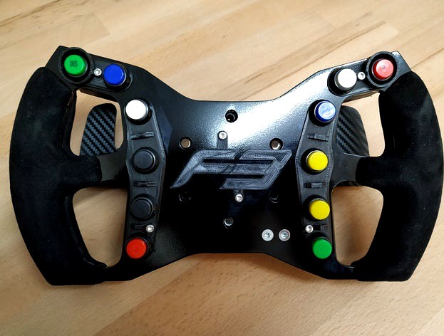
Formula B1 - (Sim racing) steering wheel
by Thingiverse
Last crawled date: 4 years, 2 months ago
Introduction
I have been planning to build a formula wheel for quite some time. Finally found the time to design and build something. While this is my first custom wheel, I'm happy with how it all turned out. I spend many hours designing and building this wheel but I like to share and give back to the community. I hope you too are able to build this awesome steering wheel and or get inspired to design you own.
How to
I will try to write down a brief how to. In principle this wheel is build using similar techniques as Amstudio - HOW TO MAKE A DIY AUDI DTM STEERING WHEEL, just search YouTube for the video. I will try to keep improving this guide if things are unclear. But I can't explain everything in full detail here I guess, so you might have to look up some things elsewhere.
Cut the base plate
I made the base plate using basic tools, but if you have access to a laser, water or CNC cutter the end result will be even nicer. But its definitely doable using the following basic tools: jig saw, file(s) or rotary tool, drill, etc. The steps below show the process I used to cut the base plate.
Print the "Formula B1 - Base Drawing.pdf"
Make sure it's printed at 100% and not scale up or down
You can check this by measuring the 70mm bolt pattern
Use a pair of scissors to cut out the outer and inner shape
Use some glue to glue the design to the aluminium base plate
Cut out the shape using a jig saw
Use a file or rotary tool with mill to smooth the edges
Drill the holes
Use a bit of sandpaper to finish the edges and holes
Paint or wrap the base plate
I didn't like the look of the plain aluminium, but if you like it you can move to the next step. If you're like me, you have a couple options. You can do what I did and use spray paint to paint the aluminium black (apply some primer and optional clear coat as well). Or you can use (carbon) vinyl wrap for an even quicker result.
3D Print the components
This should be straightforward. Non of the 3D printed components need to be super strong. I printed everything in black PLA with an infill of 30-50%.
Assemble the shifters
To assemble the shifters follow the procedure below:
Use some super glue to glue the magnets in the lever and body
Solder two wires to each switch, one to the NO and one to the COM/GND pin
Mount each switch using two m3 bolts, two nuts and the switch mount
Push the m4 mounting nuts into the base
Fix the lever in de body by using the axle
Mount the shifter paddle to the shifter using two m3 bolts and nuts
Wrap and mount the handle bars
This step is not absolutely necessary but I think the wheel looks and feels much nicer when the handles are wrapped in suede leather. I have not used the wheel yet, but I guess its best to use gloves to keep the suede in good shape. Alternatively you could also wrap the handles in normal leather or sky/fake leather for a bit more durability.
I thought this step would be much harder, but I'm really satisfied with end result. I guess having the right glue is the most important thing. I ordered the exact same glue as Amstudio uses for his wheels: Multibond - contact adhesive shoe fix. Other glues might work fine as well, but this is just the one I can recommend. Furthermore, I sanded the 3D printed handles a little bit to have better adhesion.
For instruction on how to do the actual wrap, the YouTube video's by Amstudio are a good starting point. One important thing to note: put in the nuts (with some glue) BEFORE applying the (suede) leather wrap.
Once you have wrapped the handles, use a utility knife to make the holes in the back of the handles and mount the handles to the base using six m3 bolts.
Wrap the 3D printed enclosure
This step is optional as well. But if you like you can wrap the bottom of the 3D printed enclosure for a nice carbon look.
Make the (coiled) USB cable
Since I was unable to find good quality coiled cable for a reasonable price I made one myself. You can find some tutorials on Youtube on how to do this (you just need a heat gun/hairdryer and optional a drill). The next step is to cut the device connector (so keep the standard A male connector) from the cable, and strip down the wires. Now you can solder the wires of the USB cable to you 4-pin aviation connector (female side). I would recommend to use the following pinout:
USB VCC -> pin 1 GX12
USB Data- -> pin 2 GX12
USB Data+ -> pin 3 GX12
USB GND -> pin 4 GX12
Mount the Arduino and aviation connector
Depending on where you bought the Arduino screw terminal board you might have to solder the board first. Once this is done follow the steps below:
Use a file to make the bottom of the Arduino screw terminal board as flat as possible
Use some material for isolation between the board and the base. I used double sided tape for this.
Use two m3 bolts and nuts to mount the Arduino screw terminal board to the base (don't forget to add the F3 logo if you like that)
Press the Arduino Pro Micro into the screw terminal board
Mount the connector mount to the base using two m4 bolts and nuts
Cut a micro USB cable to the right length (approximately 5 cm)
Put the cable through the hole of the connector mount
Strip the cable and solder the wires to the GX12 aviation connector (male side)
Use the same pinout as described at Make the (coiled) USB cable
Mount the GX12 aviation connector on the connector mount
Plug the micro USB cable into the Arduino
The first 2 steps are just to prevent the board from making shorts with the base plate. This does not apply when using a carbonfiber base I guess. Moreover, while writing down this guide I figured that you could also use a couple small (plastic) standoffs. This is actually a nicer/easier solution then the one I just proposed.
Mount the buttons and solder the button wires
Mount the buttons to the base plate and don't forget to also mount the four buttons strips. Secure the buttons with the supplied nut, I could not fit the washer (with my 5mm base) but if you can use that as well. Next up is soldering. Below the workflow I used:
Use a single wire to connect all buttons on the left side and connect this to a single GND on the Arduino
Solder separate wires to all buttons on the left side (as seen from the front)
Connect the wires of the top left to bottom left buttons to pins: 2, 3, 4, 5, 6, 7
Use a single wire to connect all buttons on the right side and connect this to a single GND on the Arduino
Solder separate wires to all buttons on the right side (as seen from the front)
Connect the wires of the top right to bottom right buttons: 21, 20, 19, 18, 15, 14
Finally I used two cable clips to make sure all cable stay in the middle and the enclose fits. You can use a couple additional tie-wraps to make the wires look even nicer. Another thing to note, make sure the wires between button 4 and 5 (and 10 and 11) are not too short. I made mine a bit too short at first and they just snapped while mounting the enclosure. This happens because of the shifter reinforcement on the inside of the enclosure box.
Add the threaded inserts to the enclose
Push the four m3 inserts into the enclose. I used a soldering iron to push them in. But perhaps you can also do it without heat. If it does not work I guess you could use a drill to make the holes a bit smaller and glue them in.
Mount the shifters to the enclosure
Use four m4 bolts to mount the shifters to the back of the enclosure box. Put the shifter wires through the little holes of the box. Connect the shifter wires to the following pins on the Arduino:
Down shift: pin 8 and pin 9
Up shift: pin 16 and 10
Program the Arduino
Download the hid_joystick_formula_b1.zip archive and extract all files. Next open the hid_joystick_formula_b1.ino file using the Arduino IDE, select the right board and port and press the upload button.
Final touches, mount to you base and "enjoy the shit out of it"
I guess you could skip this step if you're not using a direct drive base. But I added three metal tube inserts to add some strength. You need to cut three 26mm (8mm outer, 6mm inner diameter) aluminium/steel tube and insert them into the enclose. I used a little bit of super glue to prevent them from falling out.
The wheel has a regular 70mm bold pattern, you should be able to find a suitable adapter for your base (G29, T300, etc.) or just mount it directly (OSW). So mount it and enjoy the shit out of it!
Used components
Steering wheel components
1x Arduino pro micro (https://www.aliexpress.com/item/32849563958.html)
12x Push button, 12mm PBS-11B momentary (https://www.aliexpress.com/item/32957578730.html)
1x Arduino screw terminal adapter board (https://www.aliexpress.com/item/32672294696.html)
1x GX12 Aviation connector with 4 pins (https://www.aliexpress.com/item/32806393878.html)
1x (coiled) USB cable
1x Short (you only need +- 5 cm) micro USB cable
6x Side grip bolts m3 x 30
4x Box mounting bolts m3 x 12
2x Arduino mounting bolts plus nuts m3 x 12
2x Aviation connector bracket mounting bolts plus nuts m4 x 10
4x Brass m3 x 4mm inserts
3x Metal (I used aluminium) pipe inserts for extra strength 8 mm outer diameter, 6mm inner diameter and 26mm length
2x 3M Adhesive cable clamps (https://www.aliexpress.com/item/32810382367.html)
Shifter components
2x Shifter switch KW11-3Z (without lever) (https://www.aliexpress.com/item/32989342248.html)
2x Shifter axle 6mm x 31mm (https://www.aliexpress.com/item/32819282850.html)
4x Neodynium magnet 15mm x 3mm
4x Shifter mounting bolts and nuts m4 x 10
4x Shifter switch mounting bolts and nuts m3 x 12
4x Shifter paddle mounting bolts and nuts m3 x 12
NOTE I'm quite sure about all the bolt sizes but I have not disassembled my wheel to measure the bolts again. If you find a mistake could you please let me know so I can update the list.
Used materials
Base plate 5mm aluminium (approximately 30cm x 17cm)
Optional you can use 3-5 mm aluminium, steel, carbon etc.
Suede leather about 600 cm2 (4 pieces of 10cm x 15cm)
Carbonfiber vinyl wrap (https://www.aliexpress.com/item/32260499629.html)
Wire (thin is fine, no high currents)
Paint
Solder
Super glue
Leather glue (https://www.ebay.com/itm/Multibond-Shoe-Fix-Repair-20ml-Contact-Adhesive-Glue-bond-Rubber-Leather-Canvas/173710287477)
Double sided tape
Used tools
Soldering iron
Hex (allen) keys
Pair of scissors
Jig saw with aluminium blade
Drill 3, 4, 5, 12 mm
File or rotary tool with mill
Utility knife
Wrenches
Similar models
thingiverse
free

USB type B surface mount for Arduino by Droopas
...p 2:
solder wires from arduino to usb connector. glue usb connector to housing.
step 3:
mount in project box with 2 screws. done!
thingiverse
free

Ender 3 MKS Gen L frame with micro USB connector by gtortone
...gnd available on aux-1 connector (see mks genl pinout)
then use three cables to connect micro usb module to your selected pins...
thingiverse
free

Sim Racing Wheel Button Box with Magnetic Paddle Shifters by dan188
...lever arm micro switch
qty 20 - m3 (3mm) hex nut
qty 16 - m3 x 30mm socket head cap screw
qty 4 - m3 x 8mm button head cap screw
thingiverse
free

EFJohnson Viking Series Programming Cable by joshutt
...e to it.
***please note that the old jedi connector is not an exact fit. i have had some clip on and some you have to hold on.
thingiverse
free
Harris XGP/XLP Programming Cable by joshutt
...ease note that hot super glue emits fumes. the screw is a m3-.50x10. you can use a longer screw and put a wing nut on for ease.
thingiverse
free

Kossel XL 2020 USB B panel by rmoro
... the panel to the printer. the photos also show the controller board with the usb connector that came off and the repaired board.
thingiverse
free

Ahead - USB-charger by Modellaner
...nector
circuid board material
stuff for etching ( be carefull with that !!! )
soldering iron
some cables
2 * m3 screw
2 * m3 nut
thingiverse
free

DIY USB Mount Ender 4020 or 2020 by RetroCare
...cise one thats tailored with the measurements of tighter in the back and looser in the front so the usb drive won't be stuck.
thingiverse
free

Button plate for 320mm wheel by jxdot567
...ance for shifter mounting holes so you can print with 0.4mm nozzles without needing to grind down or sand the mounting screw area
thingiverse
free

Thales Liberty Programming Cable by joshutt
...ke to use some hot glue to make sure they are secure. then you can glue the pin holder into the connector. the screw is a 6-32.
B1
design_connected
free

B1
...b1
designconnected
free 3d model of b1 by odesd2 designed by odesd2 team.
turbosquid
$1

b1
...b1
turbosquid
royalty free 3d model b1 for download as fbx on turbosquid: 3d models for games, architecture, videos. (831848)
turbosquid
$1

b1
... available on turbo squid, the world's leading provider of digital 3d models for visualization, films, television, and games.
turbosquid
$15

sofa b1
...turbosquid
royalty free 3d model sofa b1 for download as max on turbosquid: 3d models for games, architecture, videos. (1283275)
turbosquid
$140

B1 Centauro
...model b1 centauro for download as max, 3ds, fbx, obj, and mat on turbosquid: 3d models for games, architecture, videos. (1650918)
turbosquid
$4

b1.jcd
... available on turbo squid, the world's leading provider of digital 3d models for visualization, films, television, and games.
turbosquid
$26

Hawser reel B1
...uid
royalty free 3d model hawser reel b1 for download as fbx on turbosquid: 3d models for games, architecture, videos. (1449883)
turbosquid
$1

bed and nightstands b1
...alty free 3d model bed and nightstands b1 for download as skp on turbosquid: 3d models for games, architecture, videos. (1569162)
3d_export
$30

B1 Battle Droid
...y successful in substantial overwhelming numbers. early versions of the model also required the use of a central control computer
turbosquid
$150

Avro Manchester B1
... available on turbo squid, the world's leading provider of digital 3d models for visualization, films, television, and games.
Sim
turbosquid
$6

sim
...osquid
royalty free 3d model sim for download as 3dm and max on turbosquid: 3d models for games, architecture, videos. (1669193)
turbosquid
$39

Sim Card
... available on turbo squid, the world's leading provider of digital 3d models for visualization, films, television, and games.
turbosquid
free

SIM Card
... available on turbo squid, the world's leading provider of digital 3d models for visualization, films, television, and games.
design_connected
$16
Deck SIM, PIM
...deck sim, pim
designconnected
de padova deck sim, pim computer generated 3d model. designed by nichetto, luca.
turbosquid
$7

smart phone and sim
...free 3d model smart phone and sim for download as 3dm and max on turbosquid: 3d models for games, architecture, videos. (1669641)
turbosquid
$35
Grameenphone Sim Card
... grameenphone sim card for download as max, fbx, obj, and 3ds on turbosquid: 3d models for games, architecture, videos. (1527884)
turbosquid
$3
Flow Leather Chair and Sim
...lty free 3d model flow leather chair and sim for download as on turbosquid: 3d models for games, architecture, videos. (1510088)
turbosquid
$19
Nokia 107 Dual SIM
... available on turbo squid, the world's leading provider of digital 3d models for visualization, films, television, and games.
turbosquid
$15
Nokia 225 Dual Sim
... available on turbo squid, the world's leading provider of digital 3d models for visualization, films, television, and games.
turbosquid
$12

Nokia 130 Dual SIM
... available on turbo squid, the world's leading provider of digital 3d models for visualization, films, television, and games.
Formula
3ddd
$1

FORMULA
...formula
3ddd
кресло , новый стиль
новый стиль - formula steel chrome
3d_ocean
$30

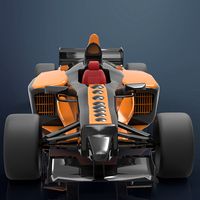
Formula F1
...ic f1 formula indianapolis indy luxury muscle race racer sedan sports street transport tuner vehicle
generic formula f1 race car.
turbosquid
$15

Fictional Formula
...
royalty free 3d model fictional formula for download as c4d on turbosquid: 3d models for games, architecture, videos. (1447537)
3d_export
$8

formula 1
...formula 1
3dexport
3d_export
$25

Formulae 3D Model
...formulae 3d model
3dexport
racing car
formulae 3d model renexito10 70729 3dexport
turbosquid
$30

Formula Cars
... available on turbo squid, the world's leading provider of digital 3d models for visualization, films, television, and games.
turbosquid
$15

Formula 40
... available on turbo squid, the world's leading provider of digital 3d models for visualization, films, television, and games.
turbosquid
$10

Formula F1
... available on turbo squid, the world's leading provider of digital 3d models for visualization, films, television, and games.
turbosquid
$10

Cheva formula
... available on turbo squid, the world's leading provider of digital 3d models for visualization, films, television, and games.
cg_studio
$80

formula car3d model
...ula f1 mclaren ferrari car race
.max .mb - formula car 3d model, royalty free license available, instant download after purchase.
Steering
3d_export
$5

steering wheel
...steering wheel
3dexport
steering wheel
3d_export
$5

steering wheel
...steering wheel
3dexport
steering wheel
3d_ocean
$2

Car steering wheel
...car steering wheel
3docean
car car wheel steering steering wheel wheel
high poly car steering wheel.
3d_ocean
$15

Steering Wheel
... all the meshes are clean and have elegent wireframe -this is a high poly detailed model ready for close up renders. – correct...
design_connected
$7

Steering Wheel
...steering wheel
designconnected
vitra steering wheel computer generated 3d model. designed by nelson, george.
turbosquid
$15

Steering Mechanism
...oyalty free 3d model steering mechanism for download as sldas on turbosquid: 3d models for games, architecture, videos. (1458880)
turbosquid
$4

Steering Wheel
...d
royalty free 3d model steering wheel for download as blend on turbosquid: 3d models for games, architecture, videos. (1562629)
turbosquid
$4

Steering wheel
...d
royalty free 3d model steering wheel for download as blend on turbosquid: 3d models for games, architecture, videos. (1376488)
turbosquid
$4

Steering Wheel
...d
royalty free 3d model steering wheel for download as blend on turbosquid: 3d models for games, architecture, videos. (1562611)
turbosquid
free

Steering Wheel
...uid
royalty free 3d model steering wheel for download as max on turbosquid: 3d models for games, architecture, videos. (1663117)
Racing
3ddd
$1
race
...race
3ddd
мотоцикл
race
turbosquid
$15
Racing
...d
royalty free 3d model racing for download as obj and blend on turbosquid: 3d models for games, architecture, videos. (1474846)
3d_export
$5
racing car
...racing car
3dexport
racing car
3d_export
$5
racing helmet
...racing helmet
3dexport
helmet 3d model for motocross or racing cars
3d_export
$5
racing car
...racing car
3dexport
low poly classical racing car model
3d_ocean
$29
racing car
...cing car rim seat speed sport sport car tyre
detailed 3d model of racing car. all materials are included. model is ready for use.
3d_ocean
$29

racing car
... rim seat speed spoiler sport sport car tire
detailed 3d model of racing car. all materials are included. model is ready for use.
3d_ocean
$15
Race Car
...race car
3docean
a very detailed and realistic 3d model of a race car, which was created with polygons.
3ddd
$1
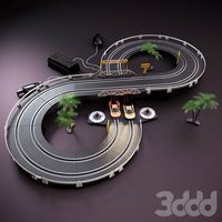
Turbo Racing
... машинка
игрушечная гоночная дорога "turbo racing". почувствуй себя настоящим гонщиком.
3d_export
$100

start race motocross
...start race motocross
3dexport
start race motocross
Wheel
archibase_planet
free
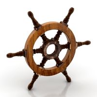
Wheel
...l steering control steering wheel
wheel ship steering wheel n060215 - 3d model (*.gsm+*.3ds+*.max) for exterior 3d visualization.
3d_ocean
$14
Wheel
...wheel
3docean
car rim car wheel rim wheel
high poly car wheel design. 16,840 polys
3d_export
free
wheel
...wheel
3dexport
wheel
3d_export
free
wheel
...wheel
3dexport
wheel
3d_export
free
Wheel
...wheel
3dexport
wheel
3d_export
$5

wheel
...wheel
3dexport
wheel for car.
3d_export
$5
wheel
...wheel
3dexport
car wheel
3d_export
$5
wheel
...wheel
3dexport
car wheel
3d_export
$5
wheel
...wheel
3dexport
car wheel
3d_export
$5
wheel
...wheel
3dexport
car wheel