Thingiverse
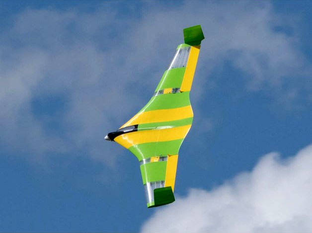
Flying Wing Buratinu by wersy
by Thingiverse
Last crawled date: 3 years ago
The Buratinu is a smaller derivate of the Buratino which was designed by Bil in St. Petersburg.
Thank you Bil for the great design.
With its pointed nose I was optimistic that I would manage the CG problem, which is always tricky with printed planes.
The original has a wingspan of 1800 mm. I designed it for a wingspan of 1300 mm with slightly more sweep back.
The video is on YouTube https://www.youtube.com/watch?v=HTmxjgw0Mq4&t=165s
Helmut uploaded a great video to show how to launch it by hand:
And this is the exciting maiden of Peter's Buratinu - inclusive stress test ;)
Detailed information about the development from the beginning and a lot pictures of the parts can be found on rc-networkhttp://www.rc-network.de/forum/showthread.php/682097-Drohne-aus-St-Petersburg-drucken
Recommended Print Settings
Attention
The wings are designed to print using 0.5 mm width, 4 bottom and 4 top
layers, no infill, 1 perimeter only.
Should you print thinner walls, the perimeter of the upper side will not stick well enough
to the perimeter of the inner stiffening construction.
If you apply thicker walls, the perimeters will not come out continuously in one
uninterrupted turn.
The layers must build up as if you were printing in spiral vase mode. Only then you get a
smooth surface on the upper side.
If unsatisfied with the results, try out 0.49 or 0.48 width in your slices settings. It
depends whether you use Cura, Slic3r, S3D or what you have. I suggest you experiment with
some tests before printing the whole thing.
The second point is: Should you print lesser layer heights, the inner stiffening
construction will not connect well to the top and bottom layers. You will suffer a gap inbetween.
All wing parts:
layer height =0,25mm, width =0.5 mm, 1 perimeter, no infill
W1, W2: 4 bottom layer, 4 top layer
W3 servo: 3 bottom layer, 4 top layer
W4, W5: 3 bottom layer, 3 top layer
W6: 3 bottom layer, 5 top Layer
winglet
2 perimeter, layer hight =0,2 mm, width =0,5 mm, 2 botton layer, 3 top layer, 25% infill
winglet slim
2 perimeter, layer hight =0,2 mm, width =0,5 mm, 1 botton layer, 2 top layer, 6% infill
elevon inner: 6 bottom layers, spiral vase mode, no top layer
elevon outer: 3 bottom layers, spiral vase mode, no top layer
elevon joint: no bottom/top layer, spiral vase mode
All fuselage parts: layer height =0,2mm, width =0.5 mm
fuselage 1: 3 perimeters, 12 bottom layers, 3 top layers, 40% infill
fuselage 2: 3 perimeters, 2 bottom layer, 3 top layer, no infill
fuselage 3: 2 perimeters, 2 bottom layers, 3 top layers, no infill
access panel and bracket
layer height =0.2 mm, width =0,5 mm
spiral vase, no top/bottom layer
Length of carbon tubes
Diameter 8 mm
fuselage/W1/W2 front: 305 mm
fuselage/W1/W2 rear: 400 mm
W2/W3/W4: 105 mm
W4/W5: 40 mm
Diameter 6 mm
W5/W6: 59 mm
Diametern 4 mm
elevons 420 mm
Specifications
airfoils: own design
wing span: 1300 mm
wing chord: 480/140 mm
CoG: 220 mm from the front of the fuselage
overall weight: 1245 g
wing weight one side complet: 342 g
wing area: 32 dm²
wing loading: 39 g/dm²
motor: Propdrive 28-36 1200KV
propeller: Aeronaut CAM Aeronaut Carbon Classic 10 x 6"
static thrust: 1300 g (3S Lipo)
battery: Turnigy 1800 mAh 3S 40~50C Lipo
motor camber: tilted -1.5 degrees
Update 16th April 2019
Uploaded elevon parts for smaller printer
elevon inner cut
elevon rudder horn
elevon joint inner
If you want to print the wingend with the winglet in one, you can now take the following part:
W6 incl. winglet
The base of the winglet is 1.5 mm thick.
This thickness must be completely filled with solid layer. E.g. 6 solid layers each 0.25 mm high.
Update 16th April 2019
Uploaded
fuselage front mc4 sp2 hd25
stop rib
It has a motor bulkhead with 4° motor camber, 2° side pull and 4 mm holes with hole circle 25 mm.
Instead of the front pass hole there are thin bars for a stop rib for the battery.
Update 17th May 2019
Uploaded fuselage 1 mc4
It has already integrated 4° motor camber.
The hole pattern is rotated 90°.
Update 7th October 2020
For those who have a rear-mounted motor, I have designed a special fuselage nose.
fuselage 1 rear-mounted mc3
firewall rear-mounted
It has already integrated 3° motor camber.
Similar models
thingiverse
free

Delta Wilde Hummel by wersy
...se no solid bottom/top layers
acces panel brackets: print width 0.5mm, layer height 0.2mm, spiral vase no solid bottom/top layers
thingiverse
free

Speedy "Red Midi Swept Wing" by wersy
...0 mah 3s 40~50c lipo
motor camber: tilted -4 degrees
side pull: none
propeller: aeronaut cam aeronaut carbon classic 10 x 6"
thingiverse
free

Speedy Red Midi Wing by wersy
... in the slicer.
the cylinder must be printed hollow, with only 2 or 3 perimeters.
then you have to re-cut the bushing with a tap.
thingiverse
free

Buratinu Midi 13000 by wersy
...perimeter_extrusion_width = 0.5
layer_height = 0.25
perimeters = 1
fill_density = 0%
bottom_solid_layers = 4
top_solid_layers = 4
cults
free

Speedy "Red Midi Swept Wing"
...0 mah 3s 40~50c lipo
motor camber: tilted -4 degrees
side pull: none
propeller: aeronaut cam aeronaut carbon classic 10 x 6"
thingiverse
free

Speedy "Red Swept Wing" RC by wersy
...after the other, and see that you can get them out again, if needed. if both pipes are inside, the wings can not be pulled apart!
thingiverse
free

Speedy "Red Mini Wing" RC Plane by wersy
....3 layer hight
0.5 width
3 solid bottom layer, spiral vase mode
the bigger fin plate:
3 solid bottom layer
1 perimeter
10% infill
thingiverse
free

Speedy "Red Swept Wing 2" RC by wersy
...ery: turnigy 1800 mah 3s 40~50c lipo
motor camber: -4°
side pull: no
propeller: aeronaut cam aeronaut carbon classic 10 x 6"
thingiverse
free

Cookie Cutter - Star With A Hole by RadekSlowik
...yers, 2 perimeters, at least 20% infill,
pusher: 0.2 mm layers, 4 top and bottom solid layers, 2 perimeters, at least 20% infill,
thingiverse
free

Maker Mining Rig by bytestrome
...: 10
infill: 30%
t-slot nut w/ fan mount:
layer: 0.1 mm
filament: pla
perimeters: 10
top layers: 10
bottom layers: 10
infill: 30%
Buratinu
thingiverse
free
Buratinu Midi 13000 by wersy
...perimeter_extrusion_width = 0.5
layer_height = 0.25
perimeters = 1
fill_density = 0%
bottom_solid_layers = 4
top_solid_layers = 4
thingiverse
free

Buratinu Maxi 2000 by wersy
...ng the construction of the 2000 (half-shell, skid reinforcement, extended fuselage) and the many helpful suggestions - thank you!
thingiverse
free

Buratinu Maxi 1600 by wersy
...perimeter_extrusion_width = 0.5
layer_height = 0.25
perimeters = 1
fill_density = 0%
bottom_solid_layers = 4
top_solid_layers = 4
thingiverse
free

Mini Buratinu LW PLA by wersy
...m for this if the rear tubes are shortened. therefore i upload a remix of the modified rear fuselage.
fuselage rear 860 lwpla.stl
Wersy
thingiverse
free

Fan 80 mm.stl by wersy
...fan 80 mm.stl by wersy
thingiverse
just a fan 80 mm for your planning.
thingiverse
free

LED Ring Mount for Printrbot by wersy
...led ring mount for printrbot by wersy
thingiverse
this mount can be fastened on one side of the extruder.
thingiverse
free

Penholder Tubes by wersy
...one for the kids with some more tubes.
it is by far not so artfully because i am just an engineer - though i hope you like it :-)
blendswap
free

WERSI Galaxis
...ocal z direction, the lights will switch on or of. for moving the hole organ there is a squared empty.
have fun with this peace.
thingiverse
free

Carrier to carry the Printrbot by wersy
...ty small and not so heavy it is a bit cumbersome to transport because the only stiff parts are the bases connected with the rods.
thingiverse
free

Prusa I2 holder for wersy's case for RRD full graphic LCD by byteborg
...i like the rrd smart lcd and have it integrated in wersy's case. i needed a way to mount it on my prusa i2, so here it is :)
thingiverse
free

Mount for the Full Graphic Smart LCD Controller Case by wersy 2020 3030
...ing for wersy's case holes... so i designed this mount parts for this great lcd case https://www.thingiverse.com/thing:87250.
thingiverse
free

Turbo Car RC (experimental) by wersy
...be/6tzpffwsd0q
tires:http://www.makeblock.com/tire-68-5x22mm-4-packhttps://www.kiwi-electronics.nl/band-68-5x22mm-4-stuks?lang=de
thingiverse
free

Case for the Full Graphic Smart LCD Controller by wersy
...is a case for the full graphic smart lcd controller. http://www.reprapdiscount.com/home/34-full-graphic-smart-lcd-controller.html
thingiverse
free
Mini Buratinu LW PLA by wersy
...m for this if the rear tubes are shortened. therefore i upload a remix of the modified rear fuselage.
fuselage rear 860 lwpla.stl
Flying
design_connected
$13
Fly-Fly
...fly-fly
designconnected
foscarini fly-fly computer generated 3d model. designed by palomba, ludovica.
3ddd
$1

Foscarini FLY-FLY
...foscarini fly-fly
3ddd
foscarini , fly-fly
foscarini fly-fly
полигонов: 73 022
3ddd
$1

Foscarini Fly-Fly
...foscarini fly-fly
3ddd
foscarini
люстра fly-fly
3d_export
free
fly
...fly
3dexport
fly
turbosquid
$15

fly fishing fly
... available on turbo squid, the world's leading provider of digital 3d models for visualization, films, television, and games.
design_connected
free

Fly
...fly
designconnected
free 3d model of fly by alias designed by acerbis, marco.
turbosquid
$49

Fly Fly Maya Rig
...turbosquid
free 3d model fly fly maya rig for download as ma on turbosquid: 3d models for games, architecture, videos. (1182393)
design_connected
$13
Fly
...fly
designconnected
zanotta fly computer generated 3d model. designed by robson , mark .
design_connected
$13

Fly
...fly
designconnected
kartell fly computer generated 3d model. designed by laviani, ferruccio.
3d_ocean
$10
3D Fly
...3d fly
3docean
3d fly 3ds max fly
this is a 3d fly model.
Wing
3ddd
$1

The Wing
...the wing
3ddd
wing , appledesign
the wing seating by appledesignstudio
3d_export
$5

wings
...wings
3dexport
beautiful wings model.
archibase_planet
free

Wing
...wing
archibase planet
wing decoration ornament
wing angel n180215 - 3d model (*.gsm+*.3ds+*.max) for interior 3d visualization.
3ddd
$1

Wing Chair
...wing chair
3ddd
baker , wing
wing chair
3ddd
$1

Диван WING
...диван wing
3ddd
flexform , wing
модель дивана wing
производитель: flexform
3ddd
$1

Диван WING
...диван wing
3ddd
flexform , wing
модель дивана wing
производитель: flexform
3ddd
$1

Кушетка WING
...кушетка wing
3ddd
flexform , wing
модель дкушетки wing
производитель: flexform
turbosquid
free

A-Wing
...id
free 3d model a-wing for download as fbx and unitypackage on turbosquid: 3d models for games, architecture, videos. (1164828)
3ddd
$1

Кресло Wing
...кресло wing
3ddd
wing
кресло wing из каталога в двух сочетаниях конфигурации.
3d_export
$5

wing nut
...wing nut
3dexport
wing nut