Thingiverse

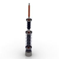
Flowerpot Antenna Housing by echicken
by Thingiverse
Last crawled date: 2 years, 10 months ago
Basically this design but with a purpose-built housing. I didn't want to mount my antenna in an oversized tube, secure it with fishing line, or drill holes in PVC pipe. The resulting antenna is fairly slim and has (thus far) performed and held together well.
Materials:
8 x M5 x 20mm screws
8 x M5 nuts
3 x 2.5mm-wide zip ties
2.5 M (8.25 feet) of RG-58C/U coax
Copper tape or aluminum foil, 235mm x 45mm
RF connector of your choosing
Mast roughly 23 mm OD (I used a scrap of 1/2" PVC pipe)
Adhesive to bond sections together (I used gel superglue)
Choose your filament wisely. It will need to withstand UV and the elements. Some pigments may affect the filament's RF properties; clear or 'natural' may be best, YMMV.
Don't insert nuts into all of the available slots. The screws only need to terminate in nuts. Extra slots, and provisions for a mast set-screws have been made in case it helps with your installation.
Some of the file names are obvious. The others, s1 through s7, are numbered 'sections' that the element is fed through. s1 mates with the coil form, s2 mates with s1, and so on. The inner diameter of s4 - s7 is smaller than s1 - s3 to prevent slackness or kinking of the stripped section of cable. s4 is slightly longer than s5 - s7.
Plan your assembly carefully, gluing sections together ahead of time in the way that works best for you. Do not glue s7 and top cap on until you are done tuning. Don't glue the coil form, s1, and bottom cap together until you're done wrapping and securing the coil. Hold coil form and s1 against a flat surface to align their mast mounts when gluing.
You'll want to print:
4 x clamp
2 x wall mount
3 x s5-s6-s7
1 x everything else
As for the rest, adapt the instructions from the above link to complete the assembly, and modify as needed to suit your installation. (Hint: when dual-banding, the foil should cover the entirety of sections s3 and s4 for starters, but may need to be repositioned or trimmed when tuning.)
I painted some "liquid tape" over the foil for weather proofing in lieu of heatshrink, which is inadvisable here. You can probably use electrical tape or plasti-dip or whatever else you come up with that doesn't involve melting the housing with a hot air gun.
OpenSCAD source included in case you want to modify.
Ask away if anything's unclear. I bashed out these instructions with little care or editing.
VE3XEC
Similar models
thingiverse
free

Infinity N3 Nesting Silhouette Markers
...s size with the same base size. so: s1, s2 (stack on s1), s3, s4, s5 (stack on s3), s6 (stack on s3 & s5), s7 (stack on s4).
thingiverse
free

CR-10 S5 / S4 Frame Brace by Pampinho
...s down at the front also with m5. (you will need to tap those threads).
i've printed mine in petg and they are plenty strong.
thingiverse
free

Audi RS/Honeycomb Grille Badge Clip - S5, S4, S3
...ave included the solidworks file if you wish to edit or remix this for pla. please submit as a remix so others can use if you do.
thingiverse
free

Samsung Galaxy S3 (S4 & S5) Wall mount by Gam30ver
...he dimensions i found online)
think i might do a kindle one next. if there is enough interest i'll upload it to thingiverse.
3dwarehouse
free

Samsung Galaxy S7 EDGE
...iphone #iphone_7 #marmo #model #modelo #motorola #new #nokia #poket #s3 #s4 #s5 #s6 #s7 #samsung #se #smartphone #teefone #update
thingiverse
free

GoPro Mount for Tronxy X1 by tothnandi
...-nuts
for the gopro section:
m5 screw
m5 nut
update!!!
gopro2.stl is a version that can be mounted on the y axis idler pulley nut
thingiverse
free

CR-10 S4 / S5 X-Axis Cable Support Bracket by OneMake
...nal file but it was very loose. so, i made this one up. same concept but a tad different. you'll need a m4 t-nut and bolt.
thingiverse
free

Tiltable Camera Mount by Geldar0124
...crew 10mm
4 x m5 nut
1 x 1/4" to 3/8" reducer bushing screw
1 x 1/4'' male to 1/4'' male threaded screw
grabcad
free

Tiltable Camera Mount
...crew 10mm
4 x m5 nut
1 x 1/4" to 3/8" reducer bushing screw
1 x 1/4'' male to 1/4'' male threaded screw
thingiverse
free

"scope" by mianiek
...32 outer diameter
screw m3, 28mm length
fishing line 0.1mm
optional:
2mm plexi
to print:
s1 x 1pcs
s2 x 2pcs
s3 x 1pcs
s4 x 2pcs
Echicken
thingiverse
free

Radial wire bender by echicken
...ingiverse
bend wire to a particular angle. includes groove for more gooder more secure wire slotting.
openscad source included.
thingiverse
free

Coax Coil Clip by echicken
...ap it in electrical tape.
default is sized for rg-8x, but that's easily changed (coax_od variable).
openscad source included.
thingiverse
free

Coax Hanger by echicken
...al support arm(s).
openscad source included. defaults are sized for rg-8x and kalibur pl-259 connector.
not actually guaranteed.
thingiverse
free

Bendy Banana coaxial cable bend guide by echicken
...link two or more of these together with mating tab/socket. default is sized for rg-8x, easily changed.
openscad source included.
thingiverse
free

Parallel loop element standoff by echicken
...e near future, one and then two parallel loops.) i expect to use four of these per parallel conductor.
openscad source included.
thingiverse
free

Case for NanoVNA-H and TinySA by echicken
...tion docs; mine did not come with one, but i left space for it anyway.
openscad source included if you want to make some changes.
Flowerpot
3d_export
$90

FLOWERPOT
...flowerpot
3dexport
flowerpot
archibase_planet
free

Flowerpot
...hibase planet
ornamental flowerpot flowerpot
ornamental flowerpot n260414 - 3d model (*.gsm+*.3ds) for interior 3d visualization.
archibase_planet
free

Flowerpot
...hibase planet
flowerpot ornamental flowerpot
ornamental flowerpot n010412 - 3d model (*.gsm+*.3ds) for interior 3d visualization.
archibase_planet
free

Flowerpot
...flowerpot
archibase planet
flowerpot pot
flower-pot ll - 3d model for interior 3d visualization.
3ddd
$1

Flowerpot
...flowerpot
3ddd
aivaninterior
turbosquid
$25

Flowerpot
...rbosquid
royalty free 3d model flowerpot for download as c4d on turbosquid: 3d models for games, architecture, videos. (1470422)
turbosquid
$3

flowerpot
...rbosquid
royalty free 3d model flowerpot for download as c4d on turbosquid: 3d models for games, architecture, videos. (1621464)
turbosquid
$10

Flowerpot
...lty free 3d model flowerpot for download as max, fbx, and obj on turbosquid: 3d models for games, architecture, videos. (1672554)
turbosquid
$10

flowerpots
...ty free 3d model flowerpots for download as max, obj, and fbx on turbosquid: 3d models for games, architecture, videos. (1166887)
turbosquid
$1

Flowerpot
...ree 3d model flowerpot for download as 3ds, max, obj, and fbx on turbosquid: 3d models for games, architecture, videos. (1193838)
Antenna
archibase_planet
free
Antenna
...chibase planet
antenna aerial television antenna
antenna kathrein n090913 - 3d model (*.gsm+*.3ds) for exterior 3d visualization.
archibase_planet
free
Antenna
...antenna
archibase planet
satellite antenna
antenna 1 - 3d model (*.gsm+*.3ds) for exterior 3d visualization.
archibase_planet
free
Antenna
...antenna
archibase planet
equipment satellite antenna
antenna 2 - 3d model (*.gsm+*.3ds) for exterior 3d visualization.
archibase_planet
free
Antenna
...ntenna
archibase planet
satellite antenna equipment dish aerial
antenna 3 - 3d model (*.gsm+*.3ds) for exterior 3d visualization.
archibase_planet
free
Antenna
...antenna
archibase planet
satellite antenna dish dish aerial
antenna 4 - 3d model (*.gsm+*.3ds) for exterior 3d visualization.
archibase_planet
free
Antenna
...e planet
antenna dish dish aerial
antenna c-band satellite s180-g n210612 - 3d model (*.gsm+*.3ds) for exterior 3d visualization.
3d_export
$5

car antenna
...car antenna
3dexport
car antenna, antenna, car gadgets
turbosquid
$1

antenna
...rbosquid
royalty free 3d model antenna for download as blend on turbosquid: 3d models for games, architecture, videos. (1655786)
3d_export
free

Station with antenna
...station with antenna
3dexport
station with antenna
turbosquid
$5

Antenna
...id
royalty free 3d model antenna for download as max and fbx on turbosquid: 3d models for games, architecture, videos. (1381532)
Housing
archibase_planet
free

House
...t
house residential house private house wooden house
house wooden n290815 - 3d model (*.gsm+*.3ds) for exterior 3d visualization.
archibase_planet
free

House
...use residential house private house wooden house
house wood stone n140815 - 3d model (*.gsm+*.3ds) for exterior 3d visualization.
archibase_planet
free

House
...ibase planet
house residential house building private house
house n050615 - 3d model (*.gsm+*.3ds) for exterior 3d visualization.
archibase_planet
free

House
...ibase planet
house residential house building private house
house n030615 - 3d model (*.gsm+*.3ds) for exterior 3d visualization.
archibase_planet
free

House
...ibase planet
house residential house building private house
house n230715 - 3d model (*.gsm+*.3ds) for exterior 3d visualization.
archibase_planet
free

House
...ibase planet
house residential house building private house
house n240615 - 3d model (*.gsm+*.3ds) for exterior 3d visualization.
archibase_planet
free

House
...ibase planet
house residential house building private house
house n290815 - 3d model (*.gsm+*.3ds) for exterior 3d visualization.
archibase_planet
free

House
...ibase planet
house residential house building private house
house n110915 - 3d model (*.gsm+*.3ds) for exterior 3d visualization.
archibase_planet
free

House
...ibase planet
house residential house building private house
house n120915 - 3d model (*.gsm+*.3ds) for exterior 3d visualization.
archibase_planet
free

House
...ibase planet
house residential house building private house
house n210915 - 3d model (*.gsm+*.3ds) for exterior 3d visualization.