Thingiverse
Flip-Clock
by Thingiverse
Last crawled date: 4 years, 2 months ago
GitHub repository: https://github.com/iz2k/flip-clock
3D design
PCB hardware and firmware design
Raspberry Pi software design
User Guide
Flip-Clock
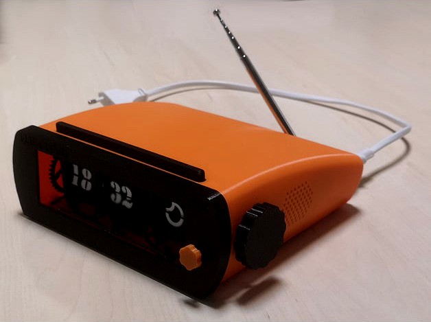
The Flip-Clock is an old stylish, classic alarm clock with up to date features, such as automatic time adjustment, weather forecast, FM radio or Spotify playback. The device consists of three 3D printed flip digits, a PCB with integrated drivers for the digit controlling stepper motors and a Raspberry Pi 3 A+ with 3W speakers to run the main code.
All the mechanics and electronics are mounted within an 3D printed elegant cover. Additionally, a snoozer bar, two rotary encoders and a RGBW LED strip are included for the user interface.
Parts
3D printed flip digits
Each flip digit consists of a support structure with two bearings. The axle is placed inside the bearings holding two flap holders. All the flaps are mounted within those holders. The movement of the digit is achieved with a stepper motor and two gears. An IR transmitter and an IR receiver are palced on the top and on the bottom of the flaps to detect transitions. Additionally, a limit switch is placed close to the gears to synchronize with it each turn.
Subparts
Support structure
Bearings (623-2RS)
Axle
Flap holders
Flaps
Gears
Stepper motor (28BYJ-48)
IR transmitter (IR diode)
IR receiver (IR photodiode)
Limit switch (CLW1093)
FlipDigitController PCB
The FlipDigitController PCB includes a microcontroller and drivers to control the stepper motors. Additionally, the PCB also handles the IR transmitter and receiver to detect flap transitions and the limit switch for automatic synchronization of the axle. The PCB has an UART interface for the abstraction layer protocol.
The current version of the PCB can handle up to two flip digits at the same time. For the FlipClock device two units of the PCB have been used: one to control hours and minutes flaps, and another one to control weather flaps.
Block diagram
Layout
Subparts
MSP430FR2433 MCU
INA333 comparators
ULN2003A drivers
3D printed cover
Subparts
3D printed top cover
3D printed bottom cover
3D printed front cover
3D printed back cover
Rotary encoders
For the user interface two rotary encoders have been used. The used encoders can detect steps in both directions, and include a built-in switch. One of the encoders is used to control the volume (up/down/mute), whereas the other encoder controls the audio device (FM Radio/Spotify/OFF)
Wheels
Encoders
Subparts
3D printed volume wheel
3D printed control wheel
TT EN11-HSM1AF15 Rotary Encoders
Snooze bar
A snooze bar is included on top of the FlipClock device. This bar can be used to trigger the nightlight by default, or to stop/snooze the alarm when it has been triggered. Tactile switches are placed under the bar to detect when it is pressed.
Bar
Switch
Subparts
3D printed snooze bar
EVQ-Q2S03W tactile switches
NeoPixel RGBW Stick
Two NeoPixel RGBW LED sticks have been included in the front of the FlipClock in order to provide nightlight and light-sign functions to the device.
Subparts
NeoPixel RGBW Stick
3W Speakers
Subparts
Stereo Enclosed Speaker Set - 3W 4 Ohm
FM radio tunner (RTL-SDR)
RTL-SDR dongle
FM antenna
Subparts
RTL-SDR dongle
FM antenna
Raspberry Pi 3 A+
Raspberry Pi 3 Model A+
Adafruit I2S 3W Stereo Speaker Bonnet
Subparts
RPI3 A+
Adafruit I2S 3W Stereo Speaker Bonnet
Power Supply
Power Supply Module
PSM Housing
Subparts
PS-05-5 power supply module
3D printed housing
Wiring
The correct wiring to connect the different electronics is as follows:
PSM connection:
Subpart
PIN
PIN
Subpart
RPI3
5V
5V
PSM
RPI3
GND
GND
PSM
NeoPixel connection:
Subpart
PIN
PIN
Subpart
NeoPixel
DIN
MOSI
RPI3
NeoPixel
5VDC
5V
RPI3
NeoPixel
GND
GND
RPI3
Snooze Bar connection:
Subpart
PIN
PIN
Subpart
Snooze Bar
SW0
GPIO 4
RPI3
Snooze Bar
SW1
GPIO 17
RPI3
Volume Encoder1 connection:
Subpart
PIN
PIN
Subpart
Volume Encoder
SW0
GPIO 24
RPI3
Volume Encoder
SW1
GPIO 25
RPI3
Volume Encoder
ROT0
GPIO 27
RPI3
Volume Encoder
ROT1
GPIO 23
RPI3
Volume Encoder
GND
GPIO 22
RPI3
Control Encoder1 connection:
Subpart
PIN
PIN
Subpart
Control Encoder
SW0
GPIO 5
RPI3
Control Encoder
SW1
GPIO 6
RPI3
Control Encoder
ROT0
GPIO 12
RPI3
Control Encoder
ROT1
GPIO 16
RPI3
Control Encoder
GND
GPIO 13
RPI3
Flip-Clock-Controller PCB:
Subpart
PIN
PIN
Subpart
RPI3
3.3V
3.3V
Flip-Clock-Controller PCB 1 (HHMM)
RPI3
3.3V
3.3V
Flip-Clock-Controller PCB 2 (WW)
RPI3
TX
RX
Flip-Clock-Controller PCB 1 (HHMM)
Flip-Clock-Controller PCB 1 (HHMM)
TX
RX
Flip-Clock-Controller PCB 2 (WW)
Flip-Clock-Controller PCB 2 (WW)
TX
RX
RPI3
1: For ease of connectivity, all pins of rotary encoders are routed to GPIOs. These GPIOs will be configured as required with pull resistors or fixed voltages via software.
3D design
PCB hardware and firmware design
Raspberry Pi software design
User Guide
Flip-Clock
The Flip-Clock is an old stylish, classic alarm clock with up to date features, such as automatic time adjustment, weather forecast, FM radio or Spotify playback. The device consists of three 3D printed flip digits, a PCB with integrated drivers for the digit controlling stepper motors and a Raspberry Pi 3 A+ with 3W speakers to run the main code.
All the mechanics and electronics are mounted within an 3D printed elegant cover. Additionally, a snoozer bar, two rotary encoders and a RGBW LED strip are included for the user interface.
Parts
3D printed flip digits
Each flip digit consists of a support structure with two bearings. The axle is placed inside the bearings holding two flap holders. All the flaps are mounted within those holders. The movement of the digit is achieved with a stepper motor and two gears. An IR transmitter and an IR receiver are palced on the top and on the bottom of the flaps to detect transitions. Additionally, a limit switch is placed close to the gears to synchronize with it each turn.
Subparts
Support structure
Bearings (623-2RS)
Axle
Flap holders
Flaps
Gears
Stepper motor (28BYJ-48)
IR transmitter (IR diode)
IR receiver (IR photodiode)
Limit switch (CLW1093)
FlipDigitController PCB
The FlipDigitController PCB includes a microcontroller and drivers to control the stepper motors. Additionally, the PCB also handles the IR transmitter and receiver to detect flap transitions and the limit switch for automatic synchronization of the axle. The PCB has an UART interface for the abstraction layer protocol.
The current version of the PCB can handle up to two flip digits at the same time. For the FlipClock device two units of the PCB have been used: one to control hours and minutes flaps, and another one to control weather flaps.
Block diagram
Layout
Subparts
MSP430FR2433 MCU
INA333 comparators
ULN2003A drivers
3D printed cover
Subparts
3D printed top cover
3D printed bottom cover
3D printed front cover
3D printed back cover
Rotary encoders
For the user interface two rotary encoders have been used. The used encoders can detect steps in both directions, and include a built-in switch. One of the encoders is used to control the volume (up/down/mute), whereas the other encoder controls the audio device (FM Radio/Spotify/OFF)
Wheels
Encoders
Subparts
3D printed volume wheel
3D printed control wheel
TT EN11-HSM1AF15 Rotary Encoders
Snooze bar
A snooze bar is included on top of the FlipClock device. This bar can be used to trigger the nightlight by default, or to stop/snooze the alarm when it has been triggered. Tactile switches are placed under the bar to detect when it is pressed.
Bar
Switch
Subparts
3D printed snooze bar
EVQ-Q2S03W tactile switches
NeoPixel RGBW Stick
Two NeoPixel RGBW LED sticks have been included in the front of the FlipClock in order to provide nightlight and light-sign functions to the device.
Subparts
NeoPixel RGBW Stick
3W Speakers
Subparts
Stereo Enclosed Speaker Set - 3W 4 Ohm
FM radio tunner (RTL-SDR)
RTL-SDR dongle
FM antenna
Subparts
RTL-SDR dongle
FM antenna
Raspberry Pi 3 A+
Raspberry Pi 3 Model A+
Adafruit I2S 3W Stereo Speaker Bonnet
Subparts
RPI3 A+
Adafruit I2S 3W Stereo Speaker Bonnet
Power Supply
Power Supply Module
PSM Housing
Subparts
PS-05-5 power supply module
3D printed housing
Wiring
The correct wiring to connect the different electronics is as follows:
PSM connection:
Subpart
PIN
PIN
Subpart
RPI3
5V
5V
PSM
RPI3
GND
GND
PSM
NeoPixel connection:
Subpart
PIN
PIN
Subpart
NeoPixel
DIN
MOSI
RPI3
NeoPixel
5VDC
5V
RPI3
NeoPixel
GND
GND
RPI3
Snooze Bar connection:
Subpart
PIN
PIN
Subpart
Snooze Bar
SW0
GPIO 4
RPI3
Snooze Bar
SW1
GPIO 17
RPI3
Volume Encoder1 connection:
Subpart
PIN
PIN
Subpart
Volume Encoder
SW0
GPIO 24
RPI3
Volume Encoder
SW1
GPIO 25
RPI3
Volume Encoder
ROT0
GPIO 27
RPI3
Volume Encoder
ROT1
GPIO 23
RPI3
Volume Encoder
GND
GPIO 22
RPI3
Control Encoder1 connection:
Subpart
PIN
PIN
Subpart
Control Encoder
SW0
GPIO 5
RPI3
Control Encoder
SW1
GPIO 6
RPI3
Control Encoder
ROT0
GPIO 12
RPI3
Control Encoder
ROT1
GPIO 16
RPI3
Control Encoder
GND
GPIO 13
RPI3
Flip-Clock-Controller PCB:
Subpart
PIN
PIN
Subpart
RPI3
3.3V
3.3V
Flip-Clock-Controller PCB 1 (HHMM)
RPI3
3.3V
3.3V
Flip-Clock-Controller PCB 2 (WW)
RPI3
TX
RX
Flip-Clock-Controller PCB 1 (HHMM)
Flip-Clock-Controller PCB 1 (HHMM)
TX
RX
Flip-Clock-Controller PCB 2 (WW)
Flip-Clock-Controller PCB 2 (WW)
TX
RX
RPI3
1: For ease of connectivity, all pins of rotary encoders are routed to GPIOs. These GPIOs will be configured as required with pull resistors or fixed voltages via software.
Similar models
cg_trader
$80

Animated Flip Clock
...lock
cg trader
3d model animated flip clock, available formats max, animated clock flip flipclock, ready for 3d animation and ot
thingiverse
free

Art Deco FM Radio with PCB
... connection pin on the encoder pin header . the updated eagle files have a four pin header which includes a connection to ground.
thingiverse
free

Large computer volume control knob by 8bitlogic
...ized usb volume knob. uses all adafruit gear: rotary encoder, trinket & gemma (temp till rev 2), and 16 pixel neopixel ring.
thingiverse
free

splitFlapClockRadio by iz2k
...sor data and calibration.
weather
weather data, location configuration and api keys.
historic
logged weather and air quality data
thingiverse
free

PC Volume Controller by 77rick77
...o uses neopixels for the backlights.
youtube: https://youtu.be/pkew7x2gmia
github: https://github.com/snr-tech-bytes/deej_encoder
thingiverse
free

TinyOLED without PCB. by Idegraaf
...connect vcc and gnd, so it would be less cables. encoder cables need solderig.
more info: http://www.thingiverse.com/thing:816376
3dwarehouse
free

clock , watch , snooze , car,
...clock , watch , snooze , car,
3dwarehouse
clock, watch, snooze.... car ????
thingiverse
free

USB Volume control by NeoCortex
...vice and send the volume-control-commands.
https://www.youtube.com/watch?v=xhzvn9zqyf4https://www.youtube.com/watch?v=zvoycb3yuw4
thingiverse
free

Shelly 1 GPIO Plug by RobClark56
... any connected sensor) is at ac-live voltage.☠️☠️
so never use this connector when the shelly1 is ac powered.
dc power is ok.
⚠️
thingiverse
free
RKade Mini by DMRadford
...tape to hold the battery leads in place during assembly. the risers in the prints will apply the pressure needed to make contact.
Flip
design_connected
$13

Flip
...flip
designconnected
poliform flip chairs computer generated 3d model. designed by carlo colombo.
3ddd
$1

Flip
...p
3ddd
flip , foscarini
настенный светильник.
высота - 31см
ширина - 28см
глубина - 13см
design_connected
$13
Flip Around
...flip around
designconnected
menu flip around computer generated 3d model. designed by norm.
design_connected
$18

Flip armchair
...flip armchair
designconnected
poliform flip armchair computer generated 3d model. designed by colombo, carlo.
3d_export
$10
Carveli flip
...carveli flip
3dexport
turbosquid
$5
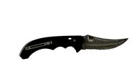
Flip Knife
...turbosquid
royalty free 3d model flip knife for download as on turbosquid: 3d models for games, architecture, videos. (1320007)
3d_export
$15

flip knife
... knife
3dexport
a 3d modelled, low poly flip knife made by me in blender. formats include: .obj, .stl, .ply, .fbx, .dae and .mtl
turbosquid
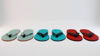
$10
Flip Flops
... free 3d model flip flops for download as blend, fbx, and obj on turbosquid: 3d models for games, architecture, videos. (1612271)
3ddd
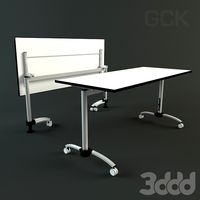
$1
Flip-Top table
...flip-top table
3ddd
стол
стол системы flip-top. 1600х700
turbosquid
$60
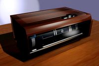
Flip Clock
... available on turbo squid, the world's leading provider of digital 3d models for visualization, films, television, and games.
Clock
3d_ocean
$4
Clock
...clock
3docean
clock hand kitchen clock time watch
a clock
archibase_planet
free

Clock
...clock
archibase planet
clock table clock alarm-clock
clock orange - 3d model (*.gsm+*.3ds) for interior 3d visualization.
archibase_planet
free

Clock
...clock
archibase planet
clock table clock alarm-clock
clock yellow - 3d model (*.gsm+*.3ds) for interior 3d visualization.
archibase_planet
free
Clock
...clock
archibase planet
clock alarm-clock
clock n100707 - 3d model for interior 3d visualization.
archibase_planet
free

Clock
...clock
archibase planet
clock table clock
clock - 3d model (*.gsm+*.3ds) for interior 3d visualization.
archibase_planet
free

Clock
...clock
archibase planet
clock striking clock
clock - 3d model (*.gsm+*.3ds) for interior 3d visualization.
archibase_planet
free

Clock
...clock
archibase planet
clock wall clock
clock 1 - 3d model (*.gsm+*.3ds) for interior 3d visualization.
archibase_planet
free
Clock
...clock
archibase planet
clock wall clock
clock 2 - 3d model (*.gsm+*.3ds) for interior 3d visualization.
archibase_planet
free

Clock
...clock
archibase planet
clock wall clock
clock 3 - 3d model (*.gsm+*.3ds) for interior 3d visualization.
archibase_planet
free
Clock
...clock
archibase planet
alarm clock alarm-clock
clock - 3d model (*.gsm+*.3ds) for interior 3d visualization.