Thingiverse

Flight sim Joystick with Hall effect sensors and Arduino by akaki
by Thingiverse
Last crawled date: 3 years, 3 months ago
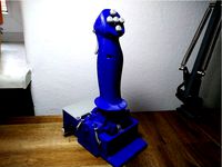
Flight stick for flight simulator games. Appears as a regular USB joystick on Windows and Mac, thanks to the Arduino Pro Micro inside. I will upload the simple code below.
Joystick position is sensed with two hall effect sensors.
Pitch and Roll axes have independent springs or rubber bands.
Goes together with 3M bolts and nuts. If you want to be fancy, you can print version B or C, which use 7 mm and 17 mm bearings, respectively.
Throttle unit: https://www.thingiverse.com/thing:4578169
Pedals: https://www.thingiverse.com/thing:4578174
Explanation video: https://youtu.be/na3NeZJYK3g
Build Instructions
Print all parts.
If you don't have bearings, print Ver A of the applicable files. If you have small 7mm x 3mm (OD*ID) bearings that go on the 3M bolts, print Ver B, if you have the larger 17mm x 6mm bearings, print Ver C.
The joystick works without any bearings, but can develop some slop in the axes after a while. I ended up using Ver C with the large bearings.
The Shaft and Hinge Cam should be printed quite slow, to get a smooth outer surface. They will slide against other parts.
All parts can be printed without supports. Except for the Joystick Grip sides and Shaft Ver C, which needs supports where touching the build plate.
Glue the magnets into the Hinge piece. Check the video. The two magnets should be attracting each other when in place (S facing N). Other than that, orientation doesn't matter.
For Ver C, the pitch axis magnets mount onto a seperate magnet holder.
Mount Shaft to Hinge.
Ver B: first, push bearings onto both sides of Hinge.
Ver A and B: add nuts to the hexagonal holes in hinge (you can glue them if you want). Run a long M3 bolt through the whole Hinge piece, and the Shaft piece, adding washers in all locations you can. The bolt must not be so long that it protrudes from the other side in between the magnets. You can add washers or a nut on the other side to adjust the length.
Ver C: Push in two bearings to Hinge. Put Shaft through Hinge, and then slide in the Axis from the side with the magnets. If the Axis doesn't seem solid enough, you can add a M3 bolt through the hole in the side of Shaft.
Solder wires onto Hall effect sensors.
On my hall effect sensor, the pins were VCC, GND, and Signal in that order.
Mount Hall effect sensors
Bend the wires and mount one on the tip of the thin pedestal in Base, and one on the pedestal between the magnets in the Shaft+Hinge assembly. They will stay between the magnets but rotate around their axis.
In Ver C you mount the pitch sensor onto the end of Axis. After this you glue down the Magnet Holder to Hinge so that the magnets flank the sensor on both sides.
You can tie down the loose wires with hot glue to add strain relief.
Glue Hinge Cam to Hinge
It goes in the notch near the back.
Insert Hinge Cam Slider to Hinge.
It slides in the rectangular slot and will slide against the V shape in Shaft. Add two rubber bands or springs, and a drop of grease on the moving surfaces. Your pitch axis should now have nice spring tension.
Mount the potentiometers and switches in base. Solder wires to the pots three leads, and to the switches NO and Common. Push on the Trim Knob.
Mount Hinge onto Base with M3 bolts. Ver A and B have slots for M3 nuts. Add washers in between where necessary. Ver C has larger holes so you can add brass inserts, or perhaps heat up M3 nuts and embed those.
Mount Cam Arm onto Base with a bolt. It should go through the slot. Add a bolt and a nut to the small hole in the wall in Base, and add a rubber band or spring between that bolt and the hook in Cam Arm. Add some grease. This Cam Arm should now add spring tension to your roll axis. Your joystick shaft should now move in all directions and return to the middle.
Add a bolt for the Trigger and use hot glue to glue a microswitch to Joystick Grip Left Side. Make sure the location is good so you get a perfect trigger motion.
Slide in Thumb button and glue in a microswitch for it in Joystick Grip Left Side.
Add four Face Buttons to Joystick Grip Face Buttons Mount Plate, and hot glue four microswitches to it. Take the metallic switch arms off before gluing. (Check video to understand)
Add wires to all microswitch Common (you can solder all these together, and run one wire out), and to NO.
Glue Mount Plate onto Joystick Grip Left side.
Screw Joystick Grip Left side and Right Side together, on both sides of Shaft. Run the wires from the switches out the bottom.
Solder wires to Arduino.
Commons go to Ground. VCC goes to 5V and GND goes to GND. Pot ends go to GND and 5V. Hall effect sensor signals go to A0 and A1, pot sweepers go to A2 and A3 etc. Switch NO all go to 2, 3, 4, etc.
You can set which button and axis is which in the sketch later.
Mount Arduino to the back of Base.
Close the Base Cover.
Program Arduino. You can use this hack to change the reported Device name: http://liveelectronics.musinou.net/MIDIdeviceName.php You will have to do this if you wish to use the throttle device at the same time, the games don't understand it otherwise. Or perhaps you could use UJR.
Similar models
thingiverse
free

Hall sensor mounts for P3Steel by hinge
...ll sensor mount on the p3steel.
include:
1) hall sensor wire
2) hall sensor mount
3) magnet mount on the y-axis
print and enjoy
thingiverse
free

Thrustmaster Hotas One/4/X Yaw potentiometer to Hall Effect Sensor conversion kit by rolbista
...to the joystick shaft where yaw potentiometer is and a bracket/mount for two magnets on each side for easier orientation. big wip
thingiverse
free
Joystick with halleffect sensors pro micro by FeLep_de
...or rubberbands
microswitches
potentiometer
endstopswitch
wires
2 linear hall effect sensors
youtube: https://youtu.be/pyabw7raivi
thingiverse
free

Joystick gimbal by olukelo
...al by olukelo
thingiverse
joystick gimbal with separate axis loading with curved cams. smooth and precise. for magnetic sensors.
thingiverse
free

Sequential shifter by T-Fork
...ith a max width of 2 cm or 2x magnets and two hall effect sensors (https://www.amazon.de/dp/b07dpvtkbb?ref_=ast_sto_dp&th=1)
thingiverse
free

Simplicatron Joystick and Throttle mechanics by robv
... hand-adjusted in the technical designs to match the hardware. it most certainly will not make a perfect fit on your own printer.
thingiverse
free

Hall sensor mount for x-axis on P3Steel by hinge
...nsor mount for x-axis on p3steel by hinge
thingiverse
this is a mount for hall sensors on the metal sled of the p3steel printer.
thingiverse
free

Thrustmaster T-Flight Hotas X Joystick - Hall Effect Conversion by t_teeds
...at 90 degrees to it. use hot glue or similar to fix the sensor and wires in place on...
thingiverse
free

Pedal assist sensor for Hollowtech II by DreaMinder
...lts instead of the smallest gear.
i had to add a spacer to the hall sensor itself, to increase the distance from the magnet-disk.
thingiverse
free

Simchair MKIII anti-torque pedals by hc625ma
...nd ethernet socket pin 2
addr - sda (bus address 0x4a)
a0 - ss495a signal
scl - ethernet socket pin 3
sda - ethernet socket pin 4
Akaki
thingiverse
free

Sandwich Basket (Akaki Basket 10) by akaki
...ts from cubicdissection and my etsy shop.
openscad / puzzlecad files included.
video: https://www.youtube.com/watch?v=radwstj0ia0
thingiverse
free

Coffee Basket (Akaki Basket 9) by akaki
...ts from cubicdissection and my etsy shop.
openscad / puzzlecad files included.
video: https://www.youtube.com/watch?v=radwstj0ia0
thingiverse
free

Chicken Basket by akaki
...ion.
i printed the puzzle in pla at 0.2 mm layer height.
openscad / puzzlecad files included.
video: https://youtu.be/izh5s_ggmfi
thingiverse
free

Hamburger Basket by akaki
...ion.
i printed the puzzle in pla at 0.2 mm layer height.
openscad / puzzlecad files included.
video: https://youtu.be/izh5s_ggmfi
thingiverse
free

Salmiakki Basket by akaki
...ion.
i printed the puzzle in pla at 0.2 mm layer height.
openscad / puzzlecad files included.
video: https://youtu.be/izh5s_ggmfi
thingiverse
free

Peppermint Basket by akaki
...rinted the puzzle in pla at 0.2 mm layer height.
openscad / puzzlecad files included.
https://www.youtube.com/watch?v=radwstj0ia0
thingiverse
free

Akaki Fix Puzzle Cube by akaki
...zzlecad.
print at 0.2 mm in pla, snap or glue the pieces together according to the letters in the connectors. no supports needed.
thingiverse
free

Charcoal Basket by akaki
...arge" size is compatible with the wooden baskets from cubicdissection and my etsy shop.
openscad / puzzlecad files included.
thingiverse
free

BBQ Basket by akaki
...arge" size is compatible with the wooden baskets from cubicdissection and my etsy shop.
openscad / puzzlecad files included.
thingiverse
free

Nachos Basket by William Hu by akaki
...rinted the puzzle in pla at 0.2 mm layer height.
openscad / puzzlecad files included.
https://www.youtube.com/watch?v=radwstj0ia0
Joystick
3d_export
$8

Joystick
...joystick
3dexport
joystick copy to ps4
turbosquid
$30

Joystick
... available on turbo squid, the world's leading provider of digital 3d models for visualization, films, television, and games.
turbosquid
$20

Joystick
... available on turbo squid, the world's leading provider of digital 3d models for visualization, films, television, and games.
turbosquid
$15

Joystick
... model joystick for download as 3ds, obj, fbx, blend, and dae on turbosquid: 3d models for games, architecture, videos. (1166950)
turbosquid
free

joystick
... available on turbo squid, the world's leading provider of digital 3d models for visualization, films, television, and games.
3d_export
$25

Joystick 3D Model
...joystick 3d model
3dexport
joystick game controller
joystick 3d model ailamvnn 69692 3dexport
archive3d
free

Joystick 3D Model
...tick 3d model
archive3d
joystick game device
joystick - 3d model for interior 3d visualization.
3d_export
$5

Joystick
...joystick
3dexport
atari joystick controller<br>pbr textures<br>fbx file<br>3ds max 2021 file<br>low poly
3d_export
$5

xbox 360 joystick
...xbox 360 joystick
3dexport
xbox 360 joystick
3d_export
free

joystick vintage
...joystick vintage
3dexport
Sim
turbosquid
$6

sim
...osquid
royalty free 3d model sim for download as 3dm and max on turbosquid: 3d models for games, architecture, videos. (1669193)
turbosquid
$39

Sim Card
... available on turbo squid, the world's leading provider of digital 3d models for visualization, films, television, and games.
turbosquid
free

SIM Card
... available on turbo squid, the world's leading provider of digital 3d models for visualization, films, television, and games.
design_connected
$16

Deck SIM, PIM
...deck sim, pim
designconnected
de padova deck sim, pim computer generated 3d model. designed by nichetto, luca.
turbosquid
$7

smart phone and sim
...free 3d model smart phone and sim for download as 3dm and max on turbosquid: 3d models for games, architecture, videos. (1669641)
turbosquid
$35
Grameenphone Sim Card
... grameenphone sim card for download as max, fbx, obj, and 3ds on turbosquid: 3d models for games, architecture, videos. (1527884)
turbosquid
$3

Flow Leather Chair and Sim
...lty free 3d model flow leather chair and sim for download as on turbosquid: 3d models for games, architecture, videos. (1510088)
turbosquid
$19

Nokia 107 Dual SIM
... available on turbo squid, the world's leading provider of digital 3d models for visualization, films, television, and games.
turbosquid
$15

Nokia 225 Dual Sim
... available on turbo squid, the world's leading provider of digital 3d models for visualization, films, television, and games.
turbosquid
$12

Nokia 130 Dual SIM
... available on turbo squid, the world's leading provider of digital 3d models for visualization, films, television, and games.
Arduino
turbosquid
$7
Arduino
...turbosquid
royalty free 3d model arduino for download as max on turbosquid: 3d models for games, architecture, videos. (1197165)
turbosquid
$3
Arduino
...turbosquid
royalty free 3d model arduino for download as c4d on turbosquid: 3d models for games, architecture, videos. (1305484)
3d_export
$5
arduino satellite
...rt
this model is the exact arduino based satellite model with some basic sensors and camera modules and also includes batteries.
turbosquid
$1
Arduino UNO
...alty free 3d model arduino uno for download as , stl, and wrl on turbosquid: 3d models for games, architecture, videos. (1515932)
3d_export
$5
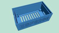
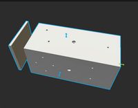
esp8266 box arduino
...esp8266 box arduino
3dexport
box for esp8266 module with wire hole. inside dimensions: 49x26 mm. height 15 mm.
3d_export
$60
Arduino Uno Rev3 Microcontroller 3D Model
...mega328p circuit board spark cable wire 5v 74v 9v 111v
arduino uno rev3 microcontroller 3d model danielgarnier4403 97237 3dexport
3d_export
free
arduino rover kit
...no!!! materials: no!!! rigged: no animated: no uv mapped: no it is not an exact copy of the original! not subject to 3d printing!
3d_ocean
$7
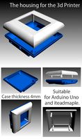
The housing for the 3d Printer
...the housing for the 3d printer 3docean arduino device housing stl the housing consists of two portions:...
3d_export
$5
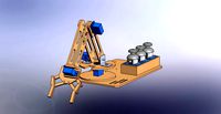
arm 4 axis
...uno -4 servo motor 180° -3 joystick (x,y) for arduino -mdf wood -some wires -cnc laser cut...
3d_export
$5
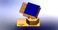
solar tracker
...machine for the frame . list of material : -arduino uno -2 step motor with driver -4 ldr sensor...
Flight
3d_export
$5
flight case
...flight case
3dexport
flight case
3ddd
$1

Zgallerie / Flight
...zgallerie / flight
3ddd
profi.кофейный , zgallerie
кофейный столик flight, zgallerie
archibase_planet
free

Flight suit
...archibase planet
flight suit clothing clothes
flight suit 2005-v3 n070712 - 3d model (*.gsm+*.3ds) for interior 3d visualization.
3ddd
$1

Flight
... zgallerie , приставной
приставной столик фирмы zgallerie
turbosquid
$19
Flight Recorder
...ee 3d model flight recorder for download as max, obj, and fbx on turbosquid: 3d models for games, architecture, videos. (1264654)
3ddd
$1
Flight Nicoletti Home
...flight nicoletti home
3ddd
nicoletti home , угловой
flight nicoletti home
turbosquid
$29
Flight of stairs
... available on turbo squid, the world's leading provider of digital 3d models for visualization, films, television, and games.
turbosquid
$20
Flight Hunter
... available on turbo squid, the world's leading provider of digital 3d models for visualization, films, television, and games.
turbosquid
$18
Flight Cases
... available on turbo squid, the world's leading provider of digital 3d models for visualization, films, television, and games.
turbosquid
$13
Flight case
... available on turbo squid, the world's leading provider of digital 3d models for visualization, films, television, and games.
Sensors
3d_export
free

parking sensor
...parking sensor
3dexport
car parking sensor
turbosquid
$1
Sensor
... available on turbo squid, the world's leading provider of digital 3d models for visualization, films, television, and games.
3d_export
$5
Smoke sensor
...port
smoke sensor, can be an impressive element for your projects. easy to use, realistic image, low polygon, quality materials.
3d_export
$5
Air Quality Sensor v1
...air quality sensor v1
3dexport
air quality sensor v1
3d_export
$15
float sensor
...e up render. - all parts and materials are logically named. other formats ================= - collada (.dae) - autodesk fbx - obj
turbosquid
$26
Wind sensor C
...free 3d model wind sensor c for download as 3ds, obj, and fbx on turbosquid: 3d models for games, architecture, videos. (1328943)
turbosquid
$26
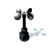
Wind sensor B
...free 3d model wind sensor b for download as 3ds, obj, and fbx on turbosquid: 3d models for games, architecture, videos. (1328168)
3d_export
$5
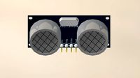
ultrasound sensor
...ultrasound sensor 3dexport ultrasonic sensors are devices that generate or sense ultrasound energy. they...
3ddd
free
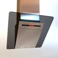
Вытяжка Shindo pallada sensor
... вытяжка
вытяжка shindo pallada sensor. в двух размерах - 600 и 900. текстуры в комплекте.
turbosquid
$52
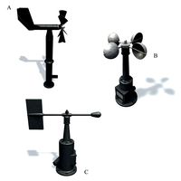
Wind sensor A B C
...
royalty free 3d model wind sensor a b c for download as fbx on turbosquid: 3d models for games, architecture, videos. (1408406)
Hall
3d_export
$5

hall
...hall
3dexport
hall
archibase_planet
free

Hall
...hall
archibase planet
hallstand hall furniture
hall n020909 - 3d model (*.gsm+*.3ds) for interior 3d visualization.
design_connected
$25

Hall
...hall
designconnected
driade hall computer generated 3d model. designed by dordoni, rodolfo.
archibase_planet
free

Hall tree
...hall tree
archibase planet
hall tree clothes tree hall-stand
hall tree n311011 - 3d model (*.3ds) for interior 3d visualization.
archibase_planet
free

Hall tree
...hall tree
archibase planet
hall tree clothes tree hall-stand
hall tree n071111 - 3d model (*.3ds) for interior 3d visualization.
archibase_planet
free

Hall tree
...hall tree
archibase planet
hall tree hall-stand clothes tree
hall tree n181112 - 3d model (*.3ds) for interior 3d visualization.
archibase_planet
free

Hall tree
...hall tree
archibase planet
hall tree hanger hall-stand
hall tree n160913 - 3d model (*.gsm+*.3ds) for interior 3d visualization.
turbosquid
$18

Hall
...ll
turbosquid
royalty free 3d model hall for download as max on turbosquid: 3d models for games, architecture, videos. (1616192)
turbosquid
$5

Hall
...ll
turbosquid
royalty free 3d model hall for download as max on turbosquid: 3d models for games, architecture, videos. (1311500)
turbosquid
$5

Hall
...ll
turbosquid
royalty free 3d model hall for download as max on turbosquid: 3d models for games, architecture, videos. (1311458)
Effect
turbosquid
free

Fire Effect
... available on turbo squid, the world's leading provider of digital 3d models for visualization, films, television, and games.
3d_ocean
$8

Galss Spheres effect
...eres effect
3docean
beautiful glass gui misc shiny special effect
glass spheres effect with gui with ar3 + mograph module needed.
3d_ocean
$1

Cracked Logo Effect
...al text
basic 3d model text effect. envato text can be changed within blender by simply editing it this is ready to render. (r2r)
3d_export
$30

girl with power effect
...ffect
3dexport
girl with power see my work on https://www.cgtrader.com/products/girl-with-power-effect https://artstn.co/m/6lbma
turbosquid
$10

c4d text effect
...id
royalty free 3d model c4d text effect for download as c4d on turbosquid: 3d models for games, architecture, videos. (1526092)
turbosquid
$3

Class Audio Effect
...
royalty free 3d model class audio effect for download as obj on turbosquid: 3d models for games, architecture, videos. (1560425)
3d_export
$10

shotmass effect
...shotmass effect
3dexport
to be honest i did not understand what kind of it was because i made it according to a template
turbosquid
$17

Line6 MM4 Effect
... available on turbo squid, the world's leading provider of digital 3d models for visualization, films, television, and games.
turbosquid
free

Mass Effect - Normandy -
... available on turbo squid, the world's leading provider of digital 3d models for visualization, films, television, and games.
3d_export
$5

Animated Effects 3D Model
... explossion aura earth quake crack cracks bomb rocket napalm geizer smoke myst
animated effects 3d model beatheart 67550 3dexport