Thingiverse
FlashForge 2016 LCD/SDCard/Keypad Interface Board Redesign by dewhisna
by Thingiverse
Last crawled date: 2 years, 12 months ago
See this thing on GitHub: https://github.com/dewhisna/LCDInterface_FFCP.
I'm tired of having SDCard read issues on my FlashForge Creator Pro 2016 printers. I have three of those printers and all three have issues. After digging through and analyzing the schematics, I think the primary culprit is either ringing or a slight timing skew between the SCLK timebase and the unbuffered MISO data output from the SDCard. SDCards aren't designed to drive their data output down a 300mm ribbon cable.
Then if you add the other issues of no bypass capacitors, limited decoupling capacitors, no ESD protection, long off-board 3.3V power runs, and abuse of a 74AHC125 as a voltage level translator, it's a wonder, as Gary described with his LCD ESD Protection board, "that it works at all".
I originally looked at just building one of Gary's LCD ESD Protection boards for each of my printers, since the circuit in my FlashForge Creator Pro 2016 printers is nearly identical to the Replicator design. But, I decided that it physically wouldn't fit the printer all that well.
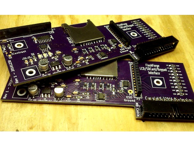
Since I had to make the boards regardless, I decided instead to completely redesign the main LCD Interface Board of the FlashForge -- which is the bottom board in the stack inside the LCD panel where the LCD and Keypad boards plug into. That board had plenty of free space on it that could be used for the additional circuitry. So, I took the circuit of the FlashForge Interface, which wasn't difficult to sketch out since it's nearly identical to the MakerBot Replicator Interface, and added the components of Gary's LCD ESD Protection board to it.
This board is the result... a new drop-in replacement for the original FlashForge LCD Interface. The only extra connection is the ESD Ground connection pad, which is designed to have a wire soldered to it and run to the chassis ground of the printer, which has a nice, convenient terminal connector in the electronics compartment of the printer near the power supply (see the posted pictures). Unlike Gary's situation, the FFCP has some metal chassis parts already and has an earth ground in place, which is really convenient.
This board also adds pads for both the red and green LEDs that have signal runs from the MightyBoard, which are completely omitted on the original FlashForge Interface. They may be useful if you are doing custom firmware coding work and need some extra LEDs for debugging and feedback -- otherwise, just don't populate them when you build this board.
I also added an option for an adjustable contrast control for the LCD, in addition to pads for the fixed resistor values that the FlashForge Interface uses. This allows you to populate it either way. If you want the simple, fixed-level contrast like the FFCP has, just populate the two fixed resistors that set that. If you want to control it manually, mount the potentiometer instead. Just don't mount both sets of components on the board or else the contrast level control will be a little wonky.
The board is nearly all surface-mount parts, but I used the larger 1206 size parts for the discrete components and I used the larger copper landing zones on all the footprints on the PCB to make it easier to hand-solder, though while assembling mine, I found the larger pads on the 1206 parts a bit annoying.
The hardest pieces to solder are the 74LVC1T45 chips, being a TSSOP-6 package with 0.65mm lead spacing. TSSOPs are easier to hand-solder than you might think, but you will need a decent soldering iron, a bright work light, a magnifier glass, and some solder wick. When assembling these boards, start with those pieces first so that the other components aren't in your way. Also, after doing the TSSOP's, the SOIC's will feel huge and so will the rest of the components.
Boards can be ordered from OSHPark: https://www.oshpark.com/shared_projects/4YWmcdYh
The schematic, bill-of-materials, and PCB Gerber files have been posted here in the files section.
Update (15-Jan-2017): I've received my boards from OSHPark and got them assembled. It came up and ran fine first time with no issues. So I've removed the "work in progress" flag.
I did make one last-minute change in the parts I used from what is posted in the bill-of-materials. I decided to use a 0.001uF (1000pF) capacitor for C2 for the loading on the SDCard SCLK signal, instead of the 0.1uF. I decided on this change after running some numbers on the signal rise-time change that the added capacitor will create for the frequencies I believe the ATmega would most likely be using for the SDCard, based largely on calculation details in the textbook "High-Speed Digital Design: A Handbook of Black Magic". As far as I know, either value will work. The 0.001uF is working fine on my boards, and Gary previously proved out the 0.1uF on the board in his design. I just felt more comfortable with the 0.001uF part. So the part I actually used for C2 was DigiKey 709-1036-1-ND.
Otherwise, my boards were assembled as-per the diagram and bill-of-materials. And I did install the ferrite cable clamp that Gary suggested, as seen in my posted pictures and included in the bill-of-materials.
So far the new board has been working with no issues and with no read errors from the SDCard. Though the original FlashForge board worked OK sometimes too, so only time will confirm if I have truly solved the SDCard issues I previously had.
If I were to make any changes to the board on a future version, I would reduce the size of the 1206 SMD pads a bit, as I found them a bit annoying during hand-soldering with them being so large, even though the larger pads supposedly facilitates hand-soldering. And, I would increase the annular ring size of the vias. The vias seem to be fine and are working well, but I always feel more comfortable being generous with design rules, and they came out a bit smaller than I had intended. And I would move the LEDs and the contrast control to the other side of the board to where they can be used with the LCD installed, making it possible to drill holes in the plastic LCD panel to access them.
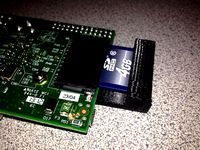
For reference, I posted a picture of my board along side the original (green) FlashForge board so you can compare them.
Update (23-Jan-2018): It's now been a full year since I built these to go on my FlashForge printers. And I'm happy to report that with these boards, I've had zero read failures from the SDCard on any of my three printers, and they've logged many hundreds of hours of printing. On the original boards that came with the printer, I experienced a read failure roughly six times out of every ten card insertions. I believe I can safely claim they have completely resolved my SDCard issues.
I'm tired of having SDCard read issues on my FlashForge Creator Pro 2016 printers. I have three of those printers and all three have issues. After digging through and analyzing the schematics, I think the primary culprit is either ringing or a slight timing skew between the SCLK timebase and the unbuffered MISO data output from the SDCard. SDCards aren't designed to drive their data output down a 300mm ribbon cable.
Then if you add the other issues of no bypass capacitors, limited decoupling capacitors, no ESD protection, long off-board 3.3V power runs, and abuse of a 74AHC125 as a voltage level translator, it's a wonder, as Gary described with his LCD ESD Protection board, "that it works at all".
I originally looked at just building one of Gary's LCD ESD Protection boards for each of my printers, since the circuit in my FlashForge Creator Pro 2016 printers is nearly identical to the Replicator design. But, I decided that it physically wouldn't fit the printer all that well.
Since I had to make the boards regardless, I decided instead to completely redesign the main LCD Interface Board of the FlashForge -- which is the bottom board in the stack inside the LCD panel where the LCD and Keypad boards plug into. That board had plenty of free space on it that could be used for the additional circuitry. So, I took the circuit of the FlashForge Interface, which wasn't difficult to sketch out since it's nearly identical to the MakerBot Replicator Interface, and added the components of Gary's LCD ESD Protection board to it.
This board is the result... a new drop-in replacement for the original FlashForge LCD Interface. The only extra connection is the ESD Ground connection pad, which is designed to have a wire soldered to it and run to the chassis ground of the printer, which has a nice, convenient terminal connector in the electronics compartment of the printer near the power supply (see the posted pictures). Unlike Gary's situation, the FFCP has some metal chassis parts already and has an earth ground in place, which is really convenient.
This board also adds pads for both the red and green LEDs that have signal runs from the MightyBoard, which are completely omitted on the original FlashForge Interface. They may be useful if you are doing custom firmware coding work and need some extra LEDs for debugging and feedback -- otherwise, just don't populate them when you build this board.
I also added an option for an adjustable contrast control for the LCD, in addition to pads for the fixed resistor values that the FlashForge Interface uses. This allows you to populate it either way. If you want the simple, fixed-level contrast like the FFCP has, just populate the two fixed resistors that set that. If you want to control it manually, mount the potentiometer instead. Just don't mount both sets of components on the board or else the contrast level control will be a little wonky.
The board is nearly all surface-mount parts, but I used the larger 1206 size parts for the discrete components and I used the larger copper landing zones on all the footprints on the PCB to make it easier to hand-solder, though while assembling mine, I found the larger pads on the 1206 parts a bit annoying.
The hardest pieces to solder are the 74LVC1T45 chips, being a TSSOP-6 package with 0.65mm lead spacing. TSSOPs are easier to hand-solder than you might think, but you will need a decent soldering iron, a bright work light, a magnifier glass, and some solder wick. When assembling these boards, start with those pieces first so that the other components aren't in your way. Also, after doing the TSSOP's, the SOIC's will feel huge and so will the rest of the components.
Boards can be ordered from OSHPark: https://www.oshpark.com/shared_projects/4YWmcdYh
The schematic, bill-of-materials, and PCB Gerber files have been posted here in the files section.
Update (15-Jan-2017): I've received my boards from OSHPark and got them assembled. It came up and ran fine first time with no issues. So I've removed the "work in progress" flag.
I did make one last-minute change in the parts I used from what is posted in the bill-of-materials. I decided to use a 0.001uF (1000pF) capacitor for C2 for the loading on the SDCard SCLK signal, instead of the 0.1uF. I decided on this change after running some numbers on the signal rise-time change that the added capacitor will create for the frequencies I believe the ATmega would most likely be using for the SDCard, based largely on calculation details in the textbook "High-Speed Digital Design: A Handbook of Black Magic". As far as I know, either value will work. The 0.001uF is working fine on my boards, and Gary previously proved out the 0.1uF on the board in his design. I just felt more comfortable with the 0.001uF part. So the part I actually used for C2 was DigiKey 709-1036-1-ND.
Otherwise, my boards were assembled as-per the diagram and bill-of-materials. And I did install the ferrite cable clamp that Gary suggested, as seen in my posted pictures and included in the bill-of-materials.
So far the new board has been working with no issues and with no read errors from the SDCard. Though the original FlashForge board worked OK sometimes too, so only time will confirm if I have truly solved the SDCard issues I previously had.
If I were to make any changes to the board on a future version, I would reduce the size of the 1206 SMD pads a bit, as I found them a bit annoying during hand-soldering with them being so large, even though the larger pads supposedly facilitates hand-soldering. And, I would increase the annular ring size of the vias. The vias seem to be fine and are working well, but I always feel more comfortable being generous with design rules, and they came out a bit smaller than I had intended. And I would move the LEDs and the contrast control to the other side of the board to where they can be used with the LCD installed, making it possible to drill holes in the plastic LCD panel to access them.
For reference, I posted a picture of my board along side the original (green) FlashForge board so you can compare them.
Update (23-Jan-2018): It's now been a full year since I built these to go on my FlashForge printers. And I'm happy to report that with these boards, I've had zero read failures from the SDCard on any of my three printers, and they've logged many hundreds of hours of printing. On the original boards that came with the printer, I experienced a read failure roughly six times out of every ten card insertions. I believe I can safely claim they have completely resolved my SDCard issues.
Similar models
thingiverse
free

LCD 12864 Full Graphic Smart LCD Controller with SDcard access for CTC / Flashforge / Makerbot printer by bogas
...ontroller.stl
spacers --- podkladki_full_graphic_smart_controller.stl
( put them between green and red pcb of the lcd )
thingiverse
free

Rostock Feet by jamesarm97
...than the motor ends. i screwed them into the m4 holes on the bottom of the motor mounts and then added a felt pad to the bottoms.
thingiverse
free

mks box 120mm fan small by Thumper72
...hinking of closing the sdcard area to being smaller as its pretty deep inside it to be able to use and i very rarely use sdcards.
thingiverse
free

Soldering reel stand by b1eiji
...iles so that you can customise the size to suit yourself however i believe the spools of solder this is designed for is standard.
thingiverse
free

Dual balanced Eurorack audio interface
...ine for you as it's not a big difference. however your mileage may vary. feel free to remix if need be.
cheerios from canada
thingiverse
free

Differential infrared z probe by MartinJS
...you might want to change the 1206 parts for smaller ones, so you can make the pcb smaller, to match the crocker board dimensions.
thingiverse
free

Filament guide for Flashforge Dremer by Plastman
...uching the cover.
the screw you need is m3 and about 20mm long as in the picture.
this maybe works on other flashforge printers.
thingiverse
free

FlashForge Creator Pro 2016 Feet by Seamongrel
...16mm bolts as they would fit as well.
i've also included a foot with a glue holder or you can just print 4 of the other foot.
thingiverse
free

individual buttons for Mmintbox by nicksears
... separate them, so modified the design to cut away the solid flat portion so it's usable as-printed. probably needs supports.
thingiverse
free

Pokemon ball SDcard holder by heerae92
...e to me if you have questions or problems.
thank you!! i'm happy to upload my design.
i don't print my design yet. sorry.
Dewhisna
thingiverse
free

K40 Laser calibration tool 2 by dewhisna
...i'm sharing it here in case anyone wants the openscad file to do further customizations without having to start from scratch.
thingiverse
free

Extended Archimedean Spiral Module by dewhisna
...pdate (9-18-2018) : changed the polygon start and end position by $fa so polygon always starts on the correct $fa angle boundary.
thingiverse
free

ArduCam Mount with Bracket by dewhisna
...ell, as is visible in the last picture below. use double-sided tape to hold the cable to the back of the printer out of the way.
thingiverse
free

OctoPi Sleeve Case for FFCP as Spool Holder Mount by dewhisna
...for additional details.
for camera mounts, this octopi case works well with this mount: https://www.thingiverse.com/thing:1763679
thingiverse
free

Power Supply (PSU) Bracket Customizations by dewhisna
...ows for the clip length to be easily altered via new 'extracliplength' variable. see the discussion in the comments tab.
thingiverse
free

The Anti-Gravitator Thru-Hole Version by dewhisna
...check yours with a volt meter before attaching the leads to the board, since reversing the power supply polarity could damage it.
thingiverse
free

LED Strip Mount for FFCP Cable Tie Screws or Standalone by dewhisna
...d to the ffcp nor to 3d printers at all. with a little customization, it can be used for mounting led strips on nearly anything.
thingiverse
free

TB6600/HY-DIV268N-5A Stepper Driver Case with 40mm Fan by dewhisna
... https://github.com/dewhisna/tb6600stepperdriver and boards can be ordered from https://www.oshpark.com/shared_projects/tkn4x7al.
thingiverse
free

Arducam Hanger for Qidi Tech 1/FFCP by malakid
...length for the arducam 5 megapixels ov5647 camera. from dewhisna i borrowed the arducam casing which was also heavily...
Sdcard
thingiverse
free

Micro SdCard, SdCard, USB Holder by Berk_3D
...micro sdcard, sdcard, usb holder by berk_3d
thingiverse
micro sdcard holder sdcard holder usb holder
thingiverse
free

SDCard Stand by uakikane
...sdcard stand by uakikane
thingiverse
sdcard stand
thingiverse
free

SDcard grill by Alleskunstenaar
...sdcard grill by alleskunstenaar
thingiverse
a robust sdcard manager
thingiverse
free

SDcard manager by Alleskunstenaar
...sdcard manager by alleskunstenaar
thingiverse
a handy vintage sdcard storage decoration piece
thingiverse
free

usb/sdcard holder by zach
...usb/sdcard holder by zach
thingiverse
a place to put your usb/sdcards btw sdcards go in the side
thingiverse
free

USB - SDCard holder by angry_nameless
...usb - sdcard holder by angry_nameless
thingiverse
usb and sdcard holder
thingiverse
free
RaspberryPi SDCard retainer by IndianaTux
...en if the raspberrypi is subjected to vibration.
as always source available on my github: https://github.com/netforces/hardware
thingiverse
free

SDCard Slot for 3dPrinter by kumodot
...int of view. so, i´ve modeled this "helper" slot for sdcard. :)
you can just fix it over the sdcard hole using 3m tape.
thingiverse
free

Gopro8 Battery/SDcard case by wimberleytech
...gopro8 battery/sdcard case by wimberleytech
thingiverse
this is a battery and micro sdcard holder for hero8 batteries
thingiverse
free

Anet A8 SDcard & Filament holder
...anet a8 sdcard & filament holder
thingiverse
sdcard & filament holder for anet a8
Keypad
turbosquid
free

Keypad
... available on turbo squid, the world's leading provider of digital 3d models for visualization, films, television, and games.
turbosquid
$19

reply systems keypad
... available on turbo squid, the world's leading provider of digital 3d models for visualization, films, television, and games.
turbosquid
free

Keypad Mobile Phone untextured
...del keypad mobile phone untextured for download as ma and fbx on turbosquid: 3d models for games, architecture, videos. (1480463)
3d_export
$17

Alarm system keypad 3D Model
... home security protection alarm digital door keypad identification equipment
alarm system keypad 3d model kreatura 92421 3dexport
turbosquid
$20

Russound UNO-S2 Keypad Switch
... available on turbo squid, the world's leading provider of digital 3d models for visualization, films, television, and games.
turbosquid
$8

Russound A-K5L Keypad with LCD Display 3D Model
... available on turbo squid, the world's leading provider of digital 3d models for visualization, films, television, and games.
3d_export
$10

ave pc-keypad
...14649 vertices) these modifiers have been applied.<br>the additional formats have been exported with the modifiers applied.
cg_studio
$16

Alarm system keypad low poly3d model
...vray max
.max .obj .fbx - alarm system keypad low poly 3d model, royalty free license available, instant download after purchase.
turbosquid
$8

Russound UNO S1 Home Audio Keypad Tuner 3D Model
... available on turbo squid, the world's leading provider of digital 3d models for visualization, films, television, and games.
turbosquid
$7

Russound KPL Advanced System Home Audio Keypad 3D Model
... available on turbo squid, the world's leading provider of digital 3d models for visualization, films, television, and games.
Flashforge
thingiverse
free

Flashforge Logo
...flashforge logo
thingiverse
flashforge logo
thingiverse
free

flashforge logo by morive3d
...flashforge logo by morive3d
thingiverse
this is a flashforge stamphttps://www.youtube.com/channel/ucu6ge9qrju9cpgg6wrlxkqw
thingiverse
free

Flashforge Glass Bed by olo2000pm
...flashforge glass bed by olo2000pm
thingiverse
flashforge glass bed
thingiverse
free
Toolbox for FlashForge Finder by Gringo1970
...toolbox for flashforge finder by gringo1970
thingiverse
smal toolbox for flashforge finder
thingiverse
free
Flashforge / Dremel lid by Disco_Rob
...flashforge / dremel lid by disco_rob
thingiverse
lid extension for the flashforge dreamer
thingiverse
free

Flashforge Dreamer Filamentguide by PeterS1
...de for flashforge dreamer / dremel idea. you need also flashforge dreamer lid spacer (http://www.thingiverse.com/thing:1219953)
thingiverse
free
Flashforge creator legs by cybadigitals
...flashforge creator legs by cybadigitals
thingiverse
these legs gives a clearance of 25mm for flashforge creator series
thingiverse
free
Flashforge Inventor/Dreamer by Iprintr7
...orge inventor/dreamer by iprintr7
thingiverse
this is my first thingiverse project and is a model of the flashforge 3d printer
thingiverse
free

Flashforge Filiment Guide by russellscanlan
...flashforge filiment guide by russellscanlan
thingiverse
my design to feed filament through the door on a flashforge adventure 3
thingiverse
free
Flashforge Winder Adapter by newky2k
...winder adapter by newky2k
thingiverse
adapters for the flashforge 0.5 kg spools to the for the filament spool winder by ssinnott
Interface
turbosquid
$18

interface
... available on turbo squid, the world's leading provider of digital 3d models for visualization, films, television, and games.
3d_export
$5

Iron man interface
...iron man interface
3dexport
iron man interface
turbosquid
$15

Audio Interface
... 3d model audio interface for download as ige, stl, and sldpr on turbosquid: 3d models for games, architecture, videos. (1425600)
turbosquid
$13

Audio interface Audient iD14
...io interface audient id14 for download as blend, fbx, and obj on turbosquid: 3d models for games, architecture, videos. (1584796)
turbosquid
$28

Interface Coco Sectional 4
...rface coco sectional 4 for download as max, max, obj, and fbx on turbosquid: 3d models for games, architecture, videos. (1588174)
turbosquid
$50

Web Interface Icon Pack
... available on turbo squid, the world's leading provider of digital 3d models for visualization, films, television, and games.
3d_export
$60

USB Keyer Audio Interface 3D Model
... television audio signal wave mic microphone shortwave meter decibal
usb keyer audio interface 3d model plutonius 20630 3dexport
turbosquid
$20

Interface Mama 2-seat Sofa
... interface mama 2-seat sofa for download as max, fbx, and obj on turbosquid: 3d models for games, architecture, videos. (1570173)
turbosquid
$10

Fantasy Truck + Syfy computer interface
...y computer interface for download as obj, fbx, blend, and dae on turbosquid: 3d models for games, architecture, videos. (1246510)
3d_export
$30

interface leon
...onfigured with pbr in mind in mind.<br>tags<br>sofa, interface, leon, cushion, plaid, chaise, lounge, leather, fabric
Redesign
3d_ocean
$45

Hyundai SUV vehicle redesigned
...was redesigned by me. 3d model was created in blender3d.preview images were rendered with realistic plugin yafaray.side view o...
turbosquid
free

Colt M16 (Redesign)
... available on turbo squid, the world's leading provider of digital 3d models for visualization, films, television, and games.
turbosquid
$30
3D for Pose Scarlet Witch redesign\para Posar redesign Feiticeira Escarlate
... imprimir redesign feiticeira escarlate for download as blend on turbosquid: 3d models for games, architecture, videos. (1700850)
3d_export
$5

Gaz 21 redesign 3D Model
...gaz 21 redesign 3d model
3dexport
gaz 21 volga
gaz 21 redesign 3d model rossergorp 71511 3dexport
turbosquid
$55

Porsche Cayman 2015 redesign
... available on turbo squid, the world's leading provider of digital 3d models for visualization, films, television, and games.
3d_ocean
$55

Gallardo superleggera redesign
...model was made with blender3d 2.62.preview images were rendered with blender3d and yafaray 0.1.2 realistic rendering engine.ob...
3d_ocean
$55
Chevy Stingray 2013 redesign
...car.i gave my best to create accurate model,but without top view image it wasn’t possible for me.so when i lost a lots of nerv...
turbosquid
$30

Redesign Crash Bandicoot (c4d,obj,max,zpr)
... available on turbo squid, the world's leading provider of digital 3d models for visualization, films, television, and games.
3ddd
$1

Tango Floor Lamp
...3ddd andrey kole , tango , castlewerks andrey kole redesign tango floor lamp by castlewerks. 3dsmax2012 - corona...
3d_export
free

flexuous tweezers
...flexuous tweezers 3dexport i just wanted to redesign a tweezers that be more interesting.<br>you can see the...
Lcd
turbosquid
$20
lcd
... available on turbo squid, the world's leading provider of digital 3d models for visualization, films, television, and games.
turbosquid
$15
LCD
... available on turbo squid, the world's leading provider of digital 3d models for visualization, films, television, and games.
turbosquid
$10
LCD
... available on turbo squid, the world's leading provider of digital 3d models for visualization, films, television, and games.
turbosquid
$10

LCD
... available on turbo squid, the world's leading provider of digital 3d models for visualization, films, television, and games.
turbosquid
$2
lcd
... available on turbo squid, the world's leading provider of digital 3d models for visualization, films, television, and games.
turbosquid
$1
lcd
... available on turbo squid, the world's leading provider of digital 3d models for visualization, films, television, and games.
turbosquid
free
lcd
... available on turbo squid, the world's leading provider of digital 3d models for visualization, films, television, and games.
turbosquid
free

LCD
... available on turbo squid, the world's leading provider of digital 3d models for visualization, films, television, and games.
3ddd
$1
Noti Lcd Sofa
...noti lcd sofa
3ddd
noti , lcd
3d model of noti lcd sofa
3d_ocean
$7

Lcd tube wall
...hrome electronic electronic lcd tv videowall
lcd tube wall you can put in the lcd your own texture or movie in it and animate it.
Board
archibase_planet
free
Board
...e planet
board information board bulletin board
board information n310813 - 3d model (*.gsm+*.3ds) for interior 3d visualization.
archibase_planet
free

Board
...board
archibase planet
board cutting board kitchen ware
board n051011 - 3d model (*.gsm+*.3ds) for interior 3d visualization.
archibase_planet
free

Board
...board
archibase planet
board blackboard school board
board school n290114 - 3d model (*.gsm+*.3ds) for interior 3d visualization.
archibase_planet
free

Board
...board
archibase planet
slate board
board - 3d model (*.gsm+*.3ds) for interior 3d visualization.
archibase_planet
free

Board
...board
archibase planet
blackboard board school furniture
board - 3d model for interior 3d visualization.
archibase_planet
free

Board
...board
archibase planet
board shelf stand
board - 3d model (*.gsm+*.3ds) for interior 3d visualization.
archibase_planet
free

Board
...board
archibase planet
kitchen ware board
board - 3d model (*.gsm+*.3ds) for interior 3d visualization.
archibase_planet
free

Board
...board
archibase planet
kitchen ware board
board n150410 - 3d model (*.gsm+*.3ds) for interior 3d visualization.
archibase_planet
free

Board
...board
archibase planet
board office supplies stationery
board - 3d model (*.gsm+*.3ds) for interior 3d visualization.
archibase_planet
free

Board
...board
archibase planet
board gym
board evminov n240613 - 3d model (*.gsm+*.3ds) for interior 3d visualization.
2016
design_connected
$27
Sydney 2016
...sydney 2016
designconnected
poliform sydney 2016 computer generated 3d model. designed by massaud, jean-marie.
turbosquid
$15

Human-2016
...turbosquid
royalty free 3d model human-2016 for download as on turbosquid: 3d models for games, architecture, videos. (1175104)
3d_export
$5

polo sedan 2016
...polo sedan 2016
3dexport
polo sedan 2016 obj
turbosquid
$35
Towel 2016
... available on turbo squid, the world's leading provider of digital 3d models for visualization, films, television, and games.
turbosquid
$6

2016-07
... available on turbo squid, the world's leading provider of digital 3d models for visualization, films, television, and games.
turbosquid
$6

2016-08
... available on turbo squid, the world's leading provider of digital 3d models for visualization, films, television, and games.
turbosquid
$6

2016-010
... available on turbo squid, the world's leading provider of digital 3d models for visualization, films, television, and games.
turbosquid
$6

2016-09
... available on turbo squid, the world's leading provider of digital 3d models for visualization, films, television, and games.
turbosquid
$6

2016-06
... available on turbo squid, the world's leading provider of digital 3d models for visualization, films, television, and games.
turbosquid
$6

2016-05
... available on turbo squid, the world's leading provider of digital 3d models for visualization, films, television, and games.