Thingiverse
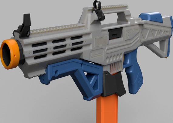
FCR-22 Taipan Assault Rifle FTW+Regular high performance foam blaster
by Thingiverse
Last crawled date: 4 years, 3 months ago
The Taipan is a printed Nerf assault rifle intended for large (300x300) build plates. No more billion little pieces to assemble or annoying flex on your blaster - this rifle is intended for those who want to get the most out of their large printers. It also offers plenty of battery and electronics space as well as an easily accessible battery compartment via a simple button press. The dual FTW+regular sized cage offers top notch performance while integrating inside the blaster seamlessly.
This project requires some commitment and I expect the builder to know how to wire up such a blaster. I've added .STEP files for reference and for making modded parts. When uploading those, keep the license in mind.
I should also note that selling the blaster without permission is illegal. If you are a seller interested in selling and manufacturing Taipans, please contact me directly.
Tips are highly appreciated and would help me a lot on future Nerf projects.
Feedback is very much welcome and though I might not be able to respond to everyone, I read everything. If you run into issues, I'll do my best to help.
Hardware list:
-x2 Standard Omron sized microswitch;
-4Motors of choice;
-FTW, Nightowl or Cabanossi flywheels;
-Regular sized flywheels. I used Worker ABS, not sure if anything else will fit.
-Wiring and a battery plug of choice;
-Some M2.5x10 screws or their imperial equivalent. Preferably countersunk. There are areas where longer screws could give it more strength;
-Some M2 Motor screws. You#ll need extra for some of the accessories.
-4x0.4mm compression springs or spring material;
-4x0.4mm extension springs or spring material;
-FTW solenoid;
-Some M5 screws for Picatinny attachments
-3mm pin material and a means to cut it
OPTIONAL:
-Nerfduino or an Arduino. I don't have any experience of wiring those up but I've left room for them inside the grip so it should cover your full auto needs.
Print settings:
Parts are NOT oriented for printing
Best results with Cura slicer, otherwise I can't guarantee good tolerances.
Layer height: 0.24 or lower
Perimeters: 3 or more (no reason for more than 5)
Supports: Preferably use tree supports and if not, don't forget to place the supports everywhere, not only directly above build plate
Print speed: 60mm/s works best but that will depend on your setup as well
5 or more top/bottom layers but I feel you could use less
15% infill should be good but you might be able to get away with lower percentage
Make sure moving parts fit together without friction before proceeding to the next step
Assembly instructions:
I've only done this once a month ago so this might be a bit harder for me to write and for you to follow
1) Start with the cage. Attach and wireup the motors, carefully add the flywheels.
2) Grab the receiver and start wiring up the microswitches to the cage, Solenoid and optionally a Nerfduino or an Arduino. Don't forget the battery plug. Make it longer so it will reach the end of the stock. when that's on. While doing this keep in mind the place they will be in. The microswitches will be screwed on the grip later.
3) Grab the grip and the trigger and assemble them together with a cut-to-length 3mm pin. Make sure there is very little friction.
4) Attach the grip with two screws on its back to the receiver. Make sure your control board falls inside nicely and be careful not to hit the wiring in general. Screw on the microswitches. Add the extension spring between the trigger and a dedicated screw hole right behind the rear microswitch. Test the trigger. It should first depress the rev microswitch and then press the fire microswitch.
5) Carefully drop in the solenoid. Again, be careful not to pinch the wiring or it won't fall inside all the way. After that, screw in the cage.
6) Cut a 3mm pin to the distance between the slots on the lower receiver. Attach and hold the mag release with a 4mm compression spring in its place. Optionally also add the flared magwell. All these components should have their holes lined up. Run the pin through it. Test the mag release by inserting a magazine. Screw in two motor screws on the flared magwell.
7) Screw on the stock, run the battery plug inside. Screw on the stock cap rail on it.
8) Assemble the stock cap and stock cap lock with a 4mm compression spring and a cut-to-length pin. Test fit and remove it off the stock. If it works properly, proceed.
9) At this point you should be able to test fire the blaster.
10) OPTIONAL: Attach the cheek rest on the stock with two motor screws.
11) Build the jam door assembly. The jam door lock goes into its slot with a 4mm compression spring. You should pre-compress it a bit. Put the jam door in.
12) Grab the handle and attach the angled picatinny. It's screwed on from the inside.
13) Screw on the handle on top of the receiver. You will need quite a few screws.
14) Screw on the barrel shroud.
15) Put the barrel halves together. Screw on the tip.
16) Insert the assembly inside the barrel shroud. Use the two rearmost holes on the barrel shroud to fix them in.
17) OPTIONAL: add the foregrip or iron sights. They use M5 screws to attach to the picatinny rails.
18) Enjoy!
Similar models
thingiverse
free

FRP-13 Mamba Heavy Nerf Rivals semi automatic pistol
...er by putting on the top and fixing it in place with pins. then, you slide in the barrel and fix it in by rotating it.
12) enjoy!
thingiverse
free

Paragon V1 - A Nerf Vortex Flywheel Blaster by BuffdaddyNerf
...(for motor) ftw hyperdrive solenoid two 21a microswitches or similar xt60 connector (for battery) 130 sized 3s motor (up...
thingiverse
free

FP-68S Twig Snake Extra Compact FTW flywheel pistol foam blaster
...nels with motor screws. make sure they don't grind on the magazine, otherwise you will need to trim them a little.
12) enjoy!
thingiverse
free

Demolisher Nerf Picatinny Side Rail by vwclogan
...inny side rail the demolisher. to install you need to remove the screws from inside the blaster. to attach i used 10mm m3 screws.
thingiverse
free

Base cage for Flywheel the world micro flywheels by SilverRoundIndustries
... been printed, feel free to make changes!
ftw micro flywheels: https://flywheeltheworld.com/shop/ftw-micro-flywheels-comet-white/
thingiverse
free

FP-68D Night Snake Compact dual cage FTW flywheel pistol foam blaster
...nels with motor screws. make sure they don't grind on the magazine, otherwise you will need to trim them a little.
11) enjoy!
thingiverse
free

Nerf Retaliator 25N spring spacer by wilblitz
... to make. the part should fit pretty snugly inside the stock attachment block and the spring should not rub (much) on the inside.
thingiverse
free

Nerf Talon Mag Stock by ShanEngineering
...ck attachment that prevents this from working.
requires 1 m3 screw, as well as a small pen spring for the stock lock attachment.
thingiverse
free

Stock for a Nerf Recon CS-6 blaster by Weldingrod1
...tandard nerf stock attachment, so you can easily edit the area that interfaces with the grip to customize it for another blaster.
thingiverse
free

Blaster Battery Stock which work with Worker's stock attachment
...;s stock attachment
thingiverse
blaster battery stock which work with worker's stock attachment
https://youtu.be/cvtbapcjiis
Fcr
3d_export
$60

boeing ah-64 d apache longbow
...of which being the an/apg-78 longbow millimeter-wave fire-control radar (fcr target acquisition system and the radar frequency interferometer (rfi),...
3dfindit
free

FCR Flanged Stud Type
...fcr flanged stud type
3dfind.it
catalog: accurate bushing
thingiverse
free

FCR carb fuel screw by Macwitt
...erse
stock fuel screw add on for kehin/fcr carburetors. i designed it for my 150r but it should fit most modern dirt bike carbs.
thingiverse
free

CE cover for FCR 39 MX by Keddy
...ce cover for fcr 39 mx by keddy
thingiverse
cover for the ce on the fcr39mx
thingiverse
free

TEUFEL SPEAKER HALTER CS 25 FCR Mk3 by PL_96
...ter
satelliten-lautsprecher cs 25 fcr mk3
\/\/\/\/\/\/\/\/
tiefe 9,50 cm
breite 10,00 cm
höhe 14,10 cm
gewicht 0,72 kg
thingiverse
free

Teufel holder for CS 25 FCR Mk3 by Merk_1337
...ho want to hide a longer cable behind the brackets.
i also recommend to print the knobs to hang up the speakers with 100 filling.
thingiverse
free

Support for Kingston FCR-HS3 memory reader for 3.5 bay by fermunoz
...gston fcr-hs3 memory reader for 3.5 bay by fermunoz
thingiverse
i put a piece of transparent 3mm filament to see the light ahead
thingiverse
free

Kingston FCR-SH4 card reader holder
...ents/ehknck/am_somewhat_proud_of_this_one_card_reader_mount/
if you find this useful or entertaining enough, tips are welcome. :)
thingiverse
free

Soldering Station by DerKlotz74
...soldering station by derklotz74 thingiverse https://fpv-community.de/showthread.php?41335-diy-smd-l%f6tstation-ersatz-f%fcr(weller)/page113 ...
thingiverse
free

Adapter Teufel Concept G 850 THX - Wallmount- Wandhalter CG 80 C - CG 80 FCR by Lubi90
...s00?ie=utf8&psc=1
2 stück m6 mutter
ich habe in die halterungen noch ein loch weiter unten gebohrt!
infill 20 %; 4 außenwände
Taipan
thingiverse
free

Taipan 2 Part (Elite Dangerous)
... i added the non-split version as well
this one is a challenge for fdm at 1000:1, sla may be needed here, scaled up may be better
thingiverse
free

Fill Probe Cap for AGT Vulcan / Taipan Mutant
...n probe.
anti-roll shaped and attachable to hose with a lanyard.
fits https://talontunes.com/shop/vulcan-fill-probe-male-adapter/
blendswap
free

ant
...find out just to change thetexture...damn i'm a noob :)taipan ...
thingiverse
free

Elite Dangerous Ships
...krait phantom mamba orca python sidewinder sidewinder (2 part) taipan type 10 defender type 6 transporter type 7 transporter...
thingiverse
free

Gunholder for 2 Guns when you run out of storage space by Trierscheid
...holder for two guns (feinwerkbau fwb aw93 and cz75 taipan pro tuning): you store the guns in upright position....
grabcad
free

UAV Taipan
...ckground in aviation design there will me major flaws in this model, but i only modeled it for fun....)
likes are appreciated...
grabcad
free

Taipan 40 RC Aircraft Model Engine
...taipan 40 rc aircraft model engine
grabcad
solidworks asm
cg_trader
$5

Gaming mouse - similiar design as Razer Taipan
...gaming mouse - similiar design as razer taipan
cg trader
please like and share!
it will help me at uploading more free models :d
grabcad
free

Toon Renderings RC Engin
...rc engin grabcad taipan 40 rc engine toon renderings http://grabcad.com/library/taipan40-rc-aircraft-model-engine-1 ...
Ftw
thingiverse
free

KTM FTW by wiccanburn
...ktm ftw by wiccanburn
thingiverse
decorative keychain for my favorite brand.
thingiverse
free

FTW SYL 81
...ftw syl 81
thingiverse
keychain support your local 81 red machine 1%
thingiverse
free

EVGA 1080 FTW Custom Blower Shroud
...evga 1080 ftw custom blower shroud
thingiverse
custom shroud for evga 1080/1070 ftw gpu
thingiverse
free

FF11 Bastok FTW (Symbol) by PrintsIT
...ff11 bastok ftw (symbol) by printsit
thingiverse
display your bastok pride!
thingiverse
free

nerf FTW fly wheel micro fly wheel by Dsfrick
...n replace ftw
u can set a heat shrinkable tube on it if u want more friction
ftw fly wheel micro fly wheel
use 100% infil !!!!!!!
renderosity
$10

BBW FTW 2
...leen.duf<br />
nileen.duf.png<br />
<br />
thanks for looking!<br />
<br />
aliveshecried</p>
thingiverse
free

EVGA GTX 1070 FTW Custom Backplate by CyberDen_Systems
...lways, feel free to comment and ask questions. i'm a custom pc builder so i can always make custom designs if you need them.
thingiverse
free

FTW Custom Announcer Table For Little Brother by TheAwesomerEgger
...ou might want to either paint this or use different colored filaments, it is not needed, but it will definitely look alot better.
thingiverse
free

Ocarina FTW by pattywac
...fter i walked away for approximately 30 seconds. i'm going to change a couple things and will print off a new copy by friday
thingiverse
free

Alan Buddha by Almewa
...buddha by almewa thingiverse my face on a buddha! ftw!! ...
Blaster
turbosquid
free

Blaster
...id
free 3d model blaster for download as obj, fbx, and blend on turbosquid: 3d models for games, architecture, videos. (1259706)
3d_export
free

Blaster
...blaster
3dexport
turbosquid
$35

blaster
... available on turbo squid, the world's leading provider of digital 3d models for visualization, films, television, and games.
turbosquid
$29

Blaster
...d model blaster for download as 3ds, obj, fbx, blend, and dae on turbosquid: 3d models for games, architecture, videos. (1296833)
turbosquid
$5

Blaster
... available on turbo squid, the world's leading provider of digital 3d models for visualization, films, television, and games.
turbosquid
free

blaster
... available on turbo squid, the world's leading provider of digital 3d models for visualization, films, television, and games.
turbosquid
$10

Blaster Machine
...squid
royalty free 3d model blaster machine for download as on turbosquid: 3d models for games, architecture, videos. (1407293)
3d_export
$5

Blaster 3D Model
...blaster 3d model
3dexport
blaster weapon game gun wars star shoter movie
blaster 3d model daniilbondar 93841 3dexport
3d_ocean
$15

Ghetto Blaster
...o blaster
3docean
audio boombox cassette ghettoblaster music radio stereo
fully modeled ghetto blaster including uvw texture psd.
turbosquid
$1

Alien Blaster
...id
royalty free 3d model alien blaster for download as blend on turbosquid: 3d models for games, architecture, videos. (1258055)
Assault
turbosquid
free

assault
...oyalty free 3d model assault for download as ma, fbx, and obj on turbosquid: 3d models for games, architecture, videos. (1687836)
3d_ocean
$15

Assault Rifle
...assault rifle
3docean
assault firearm gun rifle soldier war weapon
highly detailed assault rifle model.
3d_export
$10

assault rifle
...assault rifle
3dexport
assault rifle, made in a blender
3ddd
$1

Assault Robot
...assault robot
3ddd
робот
heavy armored assault robot, heavily armed.
3d_export
$20

assault rifle
...assault rifle
3dexport
a well-made assault rifle that can be suitable for both mobile games and computer games.
3d_export
$35

m4a1 assault rifle
...m4a1 assault rifle
3dexport
m4a1 assault rifle.
3d_ocean
$19

Assault Rifle
...th bullets). can be fine animated. 5531 polygons 2 textures (2048×2048): diffuse, specular, normal. a must-have for any fps game!
turbosquid
$45

Assault Rifle
...bosquid
royalty free 3d model assault rifle for download as on turbosquid: 3d models for games, architecture, videos. (1160538)
turbosquid
$22

Assault Rifle
...bosquid
royalty free 3d model assault rifle for download as on turbosquid: 3d models for games, architecture, videos. (1309457)
turbosquid
$250

Assault Rifle
...quid
royalty free 3d model assault rifle for download as obj on turbosquid: 3d models for games, architecture, videos. (1228363)
Foam
3d_export
$5

cylinder foam does not fall stand polyurethane foam
...cylinder foam does not fall stand polyurethane foam
3dexport
cylinder foam does not fall stand.<br>polyurethane foam
turbosquid
$1

Foam Gun
...urbosquid
royalty free 3d model foam gun for download as fbx on turbosquid: 3d models for games, architecture, videos. (1659619)
turbosquid
$39

Foam Hand
... available on turbo squid, the world's leading provider of digital 3d models for visualization, films, television, and games.
turbosquid
$14

Shaving Foam
... available on turbo squid, the world's leading provider of digital 3d models for visualization, films, television, and games.
turbosquid
$10

Foam Glider
... available on turbo squid, the world's leading provider of digital 3d models for visualization, films, television, and games.
turbosquid
$2

Foam Brush
... available on turbo squid, the world's leading provider of digital 3d models for visualization, films, television, and games.
turbosquid
$10

Foam fire extinguisher
...alty free 3d model foam fire extinguisher for download as max on turbosquid: 3d models for games, architecture, videos. (1700116)
design_connected
$7

TORK Foam Soap Dispenser
...tork foam soap dispenser
designconnected
tork foam soap dispenser computer generated 3d model.
turbosquid
$29

Sierra Foam Sofa
...e 3d model sierra foam sofa for download as max, fbx, and obj on turbosquid: 3d models for games, architecture, videos. (1575076)
turbosquid
$1
Sound Proofing Foam
... sound proofing foam for download as ige, obj, stl, and sldpr on turbosquid: 3d models for games, architecture, videos. (1289027)
Regular
turbosquid
$1

Regular Knife
...free 3d model regular knife for download as 3ds, obj, and fbx on turbosquid: 3d models for games, architecture, videos. (1325250)
turbosquid
$39

Regular Fruit
... available on turbo squid, the world's leading provider of digital 3d models for visualization, films, television, and games.
turbosquid
$5

Screwdriver Regular
... available on turbo squid, the world's leading provider of digital 3d models for visualization, films, television, and games.
3d_export
$5

regular stool
...regular stool
3dexport
the most common and simple stool. no unnecessary details. nice minimalistic look.
turbosquid
$14

Travel bus regular
...
royalty free 3d model travel bus regular for download as max on turbosquid: 3d models for games, architecture, videos. (1262352)
turbosquid
free

Regular pc case
... available on turbo squid, the world's leading provider of digital 3d models for visualization, films, television, and games.
turbosquid
free

Regular dining table
... available on turbo squid, the world's leading provider of digital 3d models for visualization, films, television, and games.
3d_export
$10

visionnaire palau regular
...e palau regular
3dexport
visionnaire palau regular<br>formats:<br>3d max 2018<br>3d max 2015<br>obj. rar
cg_studio
$22

Regular Toilet3d model
...o white porcelain
.obj .max .fbx .3ds - regular toilet 3d model, royalty free license available, instant download after purchase.
3ddd
$1

Regular Turkish Tea Set
... чайник
a regular turkish tea set with glasses and a stainless steel tea pot. modelled in 3dmax 2013 and rendered in vray 2,30.
Rifle
3d_ocean
$9

rifle
...rifle
3docean
gun low poly rifle soldier weapon
rifle model max 2013 and obj 1024×1024 texture lowpoly
turbosquid
$30

Rifle
...le
turbosquid
royalty free 3d model rifle for download as ma on turbosquid: 3d models for games, architecture, videos. (1161496)
turbosquid
$1

rifle
...turbosquid
royalty free 3d model rifle for download as blend on turbosquid: 3d models for games, architecture, videos. (1344661)
3d_export
$5

longfire rifle
...longfire rifle
3dexport
longfire rifle
3d_export
free

butt of the rifle
...butt of the rifle
3dexport
butt of the rifle
3d_export
free

repeater rifle
...repeater rifle
3dexport
repeater rifle
3d_export
$15

Rifle v2
...rifle v2
3dexport
assault rifle, designed for the protection and storming of objects. the rifle has a paralytic function.
turbosquid
$20

Rifle
...quid
royalty free 3d model rifle for download as obj and fbx on turbosquid: 3d models for games, architecture, videos. (1301083)
3d_export
$5

rifle sks
...rifle sks
3dexport
rifle sks simonov
turbosquid
$49

Rifle
...
royalty free 3d model rifle for download as ma, fbx, and obj on turbosquid: 3d models for games, architecture, videos. (1582428)
Performance
turbosquid
$39

Perform Komers
...osquid
royalty free 3d model perform komers for download as on turbosquid: 3d models for games, architecture, videos. (1144652)
turbosquid
free

Performance Tire
...urbosquid
free 3d model performance tire for download as obj on turbosquid: 3d models for games, architecture, videos. (1485856)
3d_export
$17

F-18 Performance
...f-18 performance
3dexport
f-18 performance
turbosquid
$25

Performance Car Wheel
...model performance car wheel for download as max, obj, and fbx on turbosquid: 3d models for games, architecture, videos. (1241997)
turbosquid
$99

The Performer"s Stage
... available on turbo squid, the world's leading provider of digital 3d models for visualization, films, television, and games.
3d_export
$60

Jackson Performer 3D Model
...rformer instrument music musical steelplay band rock heavy metal floyd rose
jackson performer 3d model rendersteel 86884 3dexport
turbosquid
$2

Performance Tyres - set 1
... free 3d model performance tyres - set 1 for download as obj on turbosquid: 3d models for games, architecture, videos. (1691988)
turbosquid
$90

National Centre for the Performing Arts
...tre for the performing arts for download as max, obj, and fbx on turbosquid: 3d models for games, architecture, videos. (1262784)
turbosquid
$39

Movit Brakes High Performance
... available on turbo squid, the world's leading provider of digital 3d models for visualization, films, television, and games.
turbosquid
$5

Performance Tire Rim and Brakes
... available on turbo squid, the world's leading provider of digital 3d models for visualization, films, television, and games.
22
3d_export
$25

rocks 22
...rocks 22
3dexport
rocks 3d model 22
turbosquid
$10

Luminaire - Lustre 22 22 Soleil
... available on turbo squid, the world's leading provider of digital 3d models for visualization, films, television, and games.
design_connected
$18

22 Bench
...22 bench
designconnected
etel interiores 22 bench benches computer generated 3d model. designed by etel carmona.
design_connected
$16

22 Chair
...22 chair
designconnected
etel interiores 22 chair chairs computer generated 3d model. designed by etel carmona.
3d_export
$6

tap-22
...tap-22
3dexport
3ddd
$1

Радиатор 22 типа
...радиатор 22 типа
3ddd
радиатор
радиатор 22 типа
3ddd
free

22 tube amplifier
...22 tube amplifier
3ddd
усилитель
22 tube amplifier
turbosquid
$35

Bracelet 22
...osquid
royalty free 3d model bracelet 22 for download as 3dm on turbosquid: 3d models for games, architecture, videos. (1548228)
turbosquid
$20

jamb 22
...turbosquid
royalty free 3d model jamb 22 for download as max on turbosquid: 3d models for games, architecture, videos. (1403875)
turbosquid
$18

Earrings 22
...osquid
royalty free 3d model earrings 22 for download as 3dm on turbosquid: 3d models for games, architecture, videos. (1548880)
High
3d_export
$15

ironman high
...ironman high
3dexport
ironman high poly
turbosquid
$49

High Heel Girl (High Poly)
... available on turbo squid, the world's leading provider of digital 3d models for visualization, films, television, and games.
turbosquid
$49

High Heel Girl (High Poly)
... available on turbo squid, the world's leading provider of digital 3d models for visualization, films, television, and games.
turbosquid
$49

High Heel Girl (High Poly)
... available on turbo squid, the world's leading provider of digital 3d models for visualization, films, television, and games.
turbosquid
$49

High Heel Girl (High Poly)
... available on turbo squid, the world's leading provider of digital 3d models for visualization, films, television, and games.
turbosquid
$49

High heel girl (High Poly)
... available on turbo squid, the world's leading provider of digital 3d models for visualization, films, television, and games.
design_connected
$16

Cantu High
...cantu high
designconnected
linbrasil cantu high computer generated 3d model. designed by rodrigues, sergio.
design_connected
$16

Koja high
...koja high
designconnected
blå station koja high computer generated 3d model. designed by mattson, fredrik.
design_connected
$16

Ribbon High
...ribbon high
designconnected
cappellini ribbon high bar stools computer generated 3d model. designed by nendo.
design_connected
$11

Garry High
...garry high
designconnected
ligne roset garry high computer generated 3d model. designed by jourdan, eric.