Thingiverse
Experimental Predator Ducts
by Thingiverse
Last crawled date: 4 years, 2 months ago
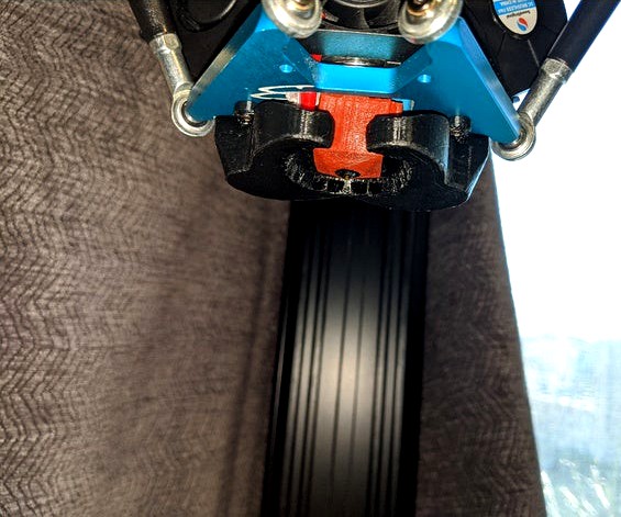
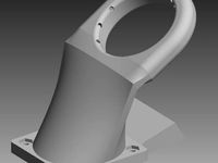
The goal of this design is to push as much air as much as possible directly under the nozzle to improve bridging and overhang performance. The idea being to have the air cool the print where the plastic will be the hottest to maximize the amount it is cooled. This does have the side effect that some of the air will be blowing on the bottom of the block, but a block sock will greatly mitigate this problem and help with the overall cooling performance. I have found that pretty much all of the other designs here either direct the air downwards where the plastic should have already solidified or just blow in the general direction of the filament nozzle and this is why I have made my own design.
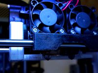
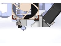
Now featuring version 5.3 one for 4020 fans and another for 4010 fans with roughly 60-80% more room airflow than version 4. They should have enough space for a v6 block(don't own one so I cannot confirm). Has 360 degree cooling similar to version 4. 5.0 and 5.1 did not fit, 5.2 was usable but I wasn't satisfied enough with it to share. MY 5015 to 4020 adapters similar to what is pictured can be fan here: https://www.thingiverse.com/thing:4132675
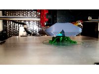
The 4010 version is just a quick and dirty adaptation of the 4020 version, not going to test or use it, but I figured I'd make one since it took like 5 minutes to modify. Added an overhang test picture that was printed using the version 5 duct, I clearly have the print temp way too high, and need to re-level the bed(just switched from PTEG to PLA), but the overhang quality is the best I have seen so far, even my Army Ant Duct doesn't do this well, print speed was a bit over 100mm/s(estimated average).
DISCLAIMER: Modify your printer at your own risk. Messing with the cooling system can cause clogs potentially to the point of damaging the hot end. Also be wary of stripping out the screw holes on the effector plate, I had one that was not formed completely and after about 10 or 20 swaps it eventually stripped, I just flipped the effector plate and cut a new slot for the wires, luckily the threads are a bit better on the other side in my case, otherwise if this happens to you you can use longer screws or even screws with nuts if it's really bad.
Your effector plate will need to be close to level if you want to use version 4 or 5, if you have any arms that longer/shorter than the rest you will want to fix this problem prior to using. Personally had one that was too long and another that was slightly too short, I just bought a replacement pair off of amazon to replace them. I made a measuring jig with a small board and finishing nails to make sure they were all close to equal. Strangely enough when I first got the printer it didn't really give me any issues, but later on I had some inconsistencies leveling the bed and this fixed that problem.
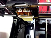
I printed them with PETG, but ABS or any other high temp plastic should be fine. I designed them with fairly thick walls on the side facing the hotend to prevent warping as I have found that thinner walled ducts, even the supplied injection molded ABS duct that sits further away and the other ducts that are available here warp/melt and so far have not had any problems with my designs melting despite the fact that they are closer to the hotend.
These models do not seem to slice correctly with anything much larger than a .4mm line width. I would also recommend preventing supports from being built inside the model, as it is very hard if not impossible to remove them. Using prusa slicer I have found that setting the support threshold to 2 degrees will prevent supports from being generated in the model and in the exhaust holes and also allow for the plate to be supported. With Cura, setting it to supports on build plate only should be good enough. Cura also seems to handle slicing these duct designs with few fuss, with Slic3r you will either need to enable or disable the detect thin walls feature depending on the design.
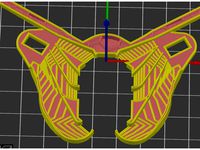
These are some of the first things I have ever made in CAD, so it's far from refined as I am still learning. It was created using Sketchup, the STL files have been fixed with 3D Builder and should be ready to slice.
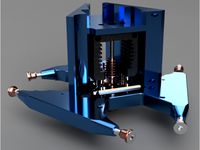
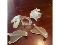
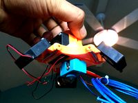
I made a demonstration model that can be hooked up to a garden hose to show the shape of the flow, it's not perfect but it does show that most of the air should flow downward below the block rather than at it. The demonstrators that are pictured here were made from my 1.4 and 3.0 designs
Version 3 should have a bit more optimized airflow compared to version 1.4 or 2, and personally the version I have been using but will soon switch over to my 5015 design here: https://www.thingiverse.com/thing:4097656
Old update: version 4.1 and 4.2, 360 degree cooling and improved internal geometry help the air flow downward a bit more. 4.2 just has a few minor tweaks to direct the airflow a bit better. You will have to take it off the bed level sensor or use my modified bed level sensor housing to re-level the bed with version 4.
Now featuring version 5.3 one for 4020 fans and another for 4010 fans with roughly 60-80% more room airflow than version 4. They should have enough space for a v6 block(don't own one so I cannot confirm). Has 360 degree cooling similar to version 4. 5.0 and 5.1 did not fit, 5.2 was usable but I wasn't satisfied enough with it to share. MY 5015 to 4020 adapters similar to what is pictured can be fan here: https://www.thingiverse.com/thing:4132675
The 4010 version is just a quick and dirty adaptation of the 4020 version, not going to test or use it, but I figured I'd make one since it took like 5 minutes to modify. Added an overhang test picture that was printed using the version 5 duct, I clearly have the print temp way too high, and need to re-level the bed(just switched from PTEG to PLA), but the overhang quality is the best I have seen so far, even my Army Ant Duct doesn't do this well, print speed was a bit over 100mm/s(estimated average).
DISCLAIMER: Modify your printer at your own risk. Messing with the cooling system can cause clogs potentially to the point of damaging the hot end. Also be wary of stripping out the screw holes on the effector plate, I had one that was not formed completely and after about 10 or 20 swaps it eventually stripped, I just flipped the effector plate and cut a new slot for the wires, luckily the threads are a bit better on the other side in my case, otherwise if this happens to you you can use longer screws or even screws with nuts if it's really bad.
Your effector plate will need to be close to level if you want to use version 4 or 5, if you have any arms that longer/shorter than the rest you will want to fix this problem prior to using. Personally had one that was too long and another that was slightly too short, I just bought a replacement pair off of amazon to replace them. I made a measuring jig with a small board and finishing nails to make sure they were all close to equal. Strangely enough when I first got the printer it didn't really give me any issues, but later on I had some inconsistencies leveling the bed and this fixed that problem.
I printed them with PETG, but ABS or any other high temp plastic should be fine. I designed them with fairly thick walls on the side facing the hotend to prevent warping as I have found that thinner walled ducts, even the supplied injection molded ABS duct that sits further away and the other ducts that are available here warp/melt and so far have not had any problems with my designs melting despite the fact that they are closer to the hotend.
These models do not seem to slice correctly with anything much larger than a .4mm line width. I would also recommend preventing supports from being built inside the model, as it is very hard if not impossible to remove them. Using prusa slicer I have found that setting the support threshold to 2 degrees will prevent supports from being generated in the model and in the exhaust holes and also allow for the plate to be supported. With Cura, setting it to supports on build plate only should be good enough. Cura also seems to handle slicing these duct designs with few fuss, with Slic3r you will either need to enable or disable the detect thin walls feature depending on the design.
These are some of the first things I have ever made in CAD, so it's far from refined as I am still learning. It was created using Sketchup, the STL files have been fixed with 3D Builder and should be ready to slice.
I made a demonstration model that can be hooked up to a garden hose to show the shape of the flow, it's not perfect but it does show that most of the air should flow downward below the block rather than at it. The demonstrators that are pictured here were made from my 1.4 and 3.0 designs
Version 3 should have a bit more optimized airflow compared to version 1.4 or 2, and personally the version I have been using but will soon switch over to my 5015 design here: https://www.thingiverse.com/thing:4097656
Old update: version 4.1 and 4.2, 360 degree cooling and improved internal geometry help the air flow downward a bit more. 4.2 just has a few minor tweaks to direct the airflow a bit better. You will have to take it off the bed level sensor or use my modified bed level sensor housing to re-level the bed with version 4.
Similar models
thingiverse
free
Anycubic Predator Mosquito Effector
...meter deeper into the effector than the original to make up for a different modification to my printer that lost me a centimeter.
thingiverse
free
Duplicator 4, Blower duct by Sam_E
...e 40x40x10 fan used previously so cools much better, great for larger overhangs. but the downside is it is a bit noisier as well.
thingiverse
free
Smart effector/Volcano Fan ducts/mounts for 2 5015 part cooling fans and 40mm heatsync fan by NCNFN3D_Arts
...rds the bottom of the heat sync to help avoid heat creep in an enclosure. so far the version i have been testing works very well.
thingiverse
free
Objekt cooling duct for i3 rework with J-Head MKV by muxa4ever
... i3 rework.
if you print it, dont use support everywhere, this blocked the airflow inside. support on the bed cause no problem.
thingiverse
free
Flashforge dual extrusion air duct by MakerUnit
...ooling fan and remove the one screw that holds the stock air duct. replace the air duct with the new one and reattach the screws.
thingiverse
free
Cooling Duct for Prusa MK3 with Slice Hot End by kmccon
... needed to go. (see pictures)
initial tests of a problem part, showed that it worked with pla at "normal" temperatures.
thingiverse
free
5015 Army Ant Duct For Anycubic Predator
...://www.thingiverse.com/thing:4060401
here's a link for my bed level sensor housing: https://www.thingiverse.com/thing:4101844
thingiverse
free
Kossel Pro E3D end effector version 3 by calviniba
...w end effectors.
i am currently on version 5, which ive uploaded under a new part page. http://www.thingiverse.com/thing:1844149
thingiverse
free
Hiprecy LEO - Part Cooling Fan Ducts by Junior_Barnes
... i printed them without supports and got a little bit of drooping across the top of the outlet but it did not affect performance.
thingiverse
free
E3D V6 Part Cooling Duct for Tronxy P802 by Duke_S
...one thing that i used to evaluate the cooling of extreme overhangs.
keep posted as i expect i will continue to keep improving it.
Predator
3d_export
$15

predator
...predator
3dexport
predator
3d_export
$18

predator
...predator
3dexport
turbosquid
$9

Predator
...r
turbosquid
royalty free 3d model predator for download as on turbosquid: 3d models for games, architecture, videos. (1322726)
3d_export
free

predator shuriken
...predator shuriken
3dexport
predator shuriken
turbosquid
$10
Predator
...d
royalty free 3d model predator for download as 3ds and obj on turbosquid: 3d models for games, architecture, videos. (1152845)
3d_export
$6
predator mask
...predator mask
3dexport
predator mask lowpoly
turbosquid
$299

Predator
... available on turbo squid, the world's leading provider of digital 3d models for visualization, films, television, and games.
3d_export
$5

mask predator
...mask predator
3dexport
an incredible mask, very detailed. based on predator. any questions write me please
3d_export
$17

MQ-1B Predator
...mq-1b predator
3dexport
mq-1b predator
3d_ocean
$5

Predator
...plane poly predator remote texture uav vehicle
ready to be used in production ready situation including all the major 3d formats.
Experimental
turbosquid
$29
Double Bass Experimental
... double bass experimental for download as blend, fbx, and obj on turbosquid: 3d models for games, architecture, videos. (1690245)
turbosquid
$15
TIE Experimental M1
... available on turbo squid, the world's leading provider of digital 3d models for visualization, films, television, and games.
3d_export
$80
Russian experimental fighter E152P 3D Model
... e152p 3d model
3dexport
aircraft experimental military fighter
russian experimental fighter e152p 3d model kors13 52215 3dexport
turbosquid
$35

Experimental space torpedo (Untextured)
... available on turbo squid, the world's leading provider of digital 3d models for visualization, films, television, and games.
turbosquid
$3
SU101 experimental Soviet artillery
... available on turbo squid, the world's leading provider of digital 3d models for visualization, films, television, and games.
turbosquid
$200
Engagement 101K Tension Experimental complete
...ment 101k tension experimental complete for download as blend on turbosquid: 3d models for games, architecture, videos. (1691565)
3d_export
$10
SU101 experimental Soviet artillery 3D Model
...type soviet russia ussr artillery world war texture textured
su101 experimental soviet artillery 3d model robby88n 31780 3dexport
turbosquid
$29

NX 2 Experimental Atomic Aircraft 3DS
... available on turbo squid, the world's leading provider of digital 3d models for visualization, films, television, and games.
3d_export
$15
experimental equipment of gas water heater
...doesn't contain parameters, but it can be edited. you can open it with solidworks 2016 and draw very good learning materials.
3d_export
$30
experimental steam engine with horizontal moving cylinder
...of separate parts of the assembly. you can independently assign mates to parts for their interaction. i answer for any questions.
Ducts
turbosquid
$19
Duct Set
...d
royalty free 3d model duct set for download as max and fbx on turbosquid: 3d models for games, architecture, videos. (1145038)
turbosquid
$10
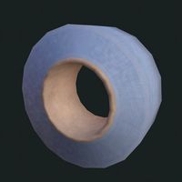
Duct Tape
...id
royalty free 3d model duct tape for download as ma and ma on turbosquid: 3d models for games, architecture, videos. (1580351)
turbosquid
free
Duct Tape
...
free 3d model duct tape for download as obj, fbx, and blend on turbosquid: 3d models for games, architecture, videos. (1486518)
3d_ocean
$7
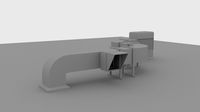
Air-duct
... ventilation
high quality industrial air duct ventilation model. created in cinema 4d but comes in various other formats as well.
turbosquid
$20
Air ducts
...lty free 3d model air ducts for download as max, obj, and fbx on turbosquid: 3d models for games, architecture, videos. (1262476)
3d_export
$10

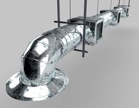
Supply air duct
...supply air duct
3dexport
supply air duct with two axial fans and hangers
turbosquid
$2
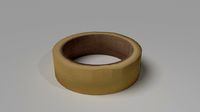
Duct Tape
...e 3d model duct tape for download as obj, fbx, blend, and dae on turbosquid: 3d models for games, architecture, videos. (1473972)
turbosquid
free
Duct Tape
... available on turbo squid, the world's leading provider of digital 3d models for visualization, films, television, and games.
3d_ocean
$3
Duct tape
...polys. includes: cinema 4d project. model in 3 formats (obj, fbx, 3ds). 6 .tga texture maps (albedo, ambient occlusion, diffus...
turbosquid
$40
Ventilation Duct PACK
...tion duct pack for download as ma, obj, fbx, and unitypackage on turbosquid: 3d models for games, architecture, videos. (1287068)