Thingiverse
Ender 4 switch box Rev2 - Boitier inter Ender 4 version 2 by Toto74
by Thingiverse
Last crawled date: 4 years, 7 months ago
Français (English below)
Il y a quelques mois j'ai mis à disposition un "Power Main Plug & ON/OFF " pour Creality Ender 4.
Ce module permettait d'avoir une fonction ON/OFF sur le 220~ et une prise pour connecter un cordon secteur.
Ce qui me génait, c'était de toujours voir les vis du bornier de raccordements...et donc laisser un risque de contact accidentel avec les doigts...
Donc aujourd'hui une évolution, qui permet et de ré-utiliser l'embase/inter de la première version ET de masquer l'accès au bornier de raccordement de l'alimentation.
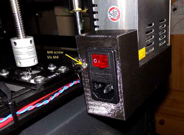
Ce boitier vient s'intégrer sous l'alimentation et en appui sur son flanc gauche. Il tient en place par une vis M4x40 dans un taraudage M4 situé d'origine sur le côté de l'alimentation.
Un perçage latéral permet de faire passer les fils 24 Vdc allant de l'alimentation à la carte-mère.
Ce boitier ON/OFF ne perturbe pas le refroidissement de l'alimentation car il n'occulte aucune ouverture d'aération. J'avais prévu de faire un petit couvercle d'obturation pour fermer complétement le côté droit, une fois monté, mais finalement je pense que le montage présent empêche déjà bien tout risque électrique.
Si cela peut servir à certains d'entre vous, j'en serais heureux
Hello Guys
Couple months ago I posted a little module named "Power Main Plug & ON/OFF " ffor Creality Ender 4 printer.
I designed it to have an ON/OFF function on the printer main, and to be able to plug/unplug and IEC main power cable.
Unfortunately, it was still possible to access power supply connectors, so stil an electrical schock hasard which did not satisfy me.
Purpose of this published item her is to solve this issue.
It allow to use the ON/OFF-plug module which was implemented into the first smal version.
With some luck (which I had) there is even no need to modify/change implemented cables on this ON/OFF switch...
A hole is here to allow 24Vdc cables to pass through from the DC power supply to the printer main board.
This new ON/OFF module is then implemented below the DC power , and fixed against the left side using a M4 x40mm screw. There is an existing M4 thread hole at this place on the power supply.... so no need to drill, modify, etc..
Once in place it hides the power supply connector and attached cables. I planed to design a little right side cover to fully close it, but I thing it is a bit useless, because with this one only, I think the electrical schock risk is almost impossible.
Hope it will be usefull for some of you!
Il y a quelques mois j'ai mis à disposition un "Power Main Plug & ON/OFF " pour Creality Ender 4.
Ce module permettait d'avoir une fonction ON/OFF sur le 220~ et une prise pour connecter un cordon secteur.
Ce qui me génait, c'était de toujours voir les vis du bornier de raccordements...et donc laisser un risque de contact accidentel avec les doigts...
Donc aujourd'hui une évolution, qui permet et de ré-utiliser l'embase/inter de la première version ET de masquer l'accès au bornier de raccordement de l'alimentation.
Ce boitier vient s'intégrer sous l'alimentation et en appui sur son flanc gauche. Il tient en place par une vis M4x40 dans un taraudage M4 situé d'origine sur le côté de l'alimentation.
Un perçage latéral permet de faire passer les fils 24 Vdc allant de l'alimentation à la carte-mère.
Ce boitier ON/OFF ne perturbe pas le refroidissement de l'alimentation car il n'occulte aucune ouverture d'aération. J'avais prévu de faire un petit couvercle d'obturation pour fermer complétement le côté droit, une fois monté, mais finalement je pense que le montage présent empêche déjà bien tout risque électrique.
Si cela peut servir à certains d'entre vous, j'en serais heureux
Hello Guys
Couple months ago I posted a little module named "Power Main Plug & ON/OFF " ffor Creality Ender 4 printer.
I designed it to have an ON/OFF function on the printer main, and to be able to plug/unplug and IEC main power cable.
Unfortunately, it was still possible to access power supply connectors, so stil an electrical schock hasard which did not satisfy me.
Purpose of this published item her is to solve this issue.
It allow to use the ON/OFF-plug module which was implemented into the first smal version.
With some luck (which I had) there is even no need to modify/change implemented cables on this ON/OFF switch...
A hole is here to allow 24Vdc cables to pass through from the DC power supply to the printer main board.
This new ON/OFF module is then implemented below the DC power , and fixed against the left side using a M4 x40mm screw. There is an existing M4 thread hole at this place on the power supply.... so no need to drill, modify, etc..
Once in place it hides the power supply connector and attached cables. I planed to design a little right side cover to fully close it, but I thing it is a bit useless, because with this one only, I think the electrical schock risk is almost impossible.
Hope it will be usefull for some of you!