Thingiverse

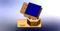
Electronics Enclosure for Arduino Mega or Rambo Mini and LCD Graphic or LCD 2004 Controller by GeoDave
by Thingiverse
Last crawled date: 3 years ago
9/7/2018
Someone commented that the Rambo Mini is a little off. Since I do not have a Rambo Mini to check this, someone else will have to tell me the correct dimensions to change this to.
5/7/2018
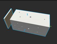
I updated the openscad file to have a 1.5mm base under the electronics board. It seemed like a better idea to give more protection to the electronics underneath rather than saving a little plastic. The module I added to the openscad code is Bottom_Flat() for those interested in that.
9/9/2017
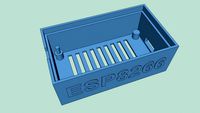
I added a vented top option for passive heat release. DD_2_TopPlateFullVented_Rev140.stl or DD_4_TopPlateFullVented_Rev140.stl
I also updated the solid top plate version to have less plastic in the middle to cut down on print time. DD_2_TopPlateFullSolid_Rev140.stl or DD_4_TopPlateFullSolid_Rev140.stl
9/7/2017
I am working on another remix to attach the raspberry Pi to the Back or Top along with the Arduino or Rambo and the LCD2004 or LCD Graphics. I am changing the front plate angle from 60 to 75 degrees to give more room on the top plate for the Pi. I also have to add a little to the height & width for a better fit. The raspberry Pi combo can now be found: https://www.thingiverse.com/thing:2525426
8/31/2017
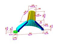
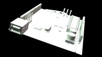
I made some major changes to the openscad file to be able to adjust the angle of the Face plate. You can now adjust that in the customizer from 45 degrees to 90. If you make any changes to the code, you will have to create new STL files of affected parts. I also added a couple of images showing how the variables work for the faceplate cutouts & the electronics mount.
8/25/2017
I changed the openscad source so it will now work with thingiverse Customizer. That should make it a lot easier for others to use that are not familiar with openscad. I have deleted all of the previous versions of the files.
There are quite a few variables you can adjust. Before you get carried away & print all the parts, I would 1st print:
DD_2_TestPrints_Rev138.stl
and DD_LeftRightBrackets_Rev138.stl.
DD types have dovetail backs & the DS types have holes for mounting to frame like a Delta printer.
The brackets have the female dovetail joints that do not change, so you will not have to reprint the left bracket if the joints are too loose or too tight.
If the dovetail joints are too tight, try the DD_4. This is a test print of the Left bracket & all the joints that connect to it. You should only need to print the left bracket once since those joints do not change, only the joints that connect to them. If you have to print a 2nd test print, You can also use the left bracket you printed for your final parts.DD_2_TestPrints_Rev138.stl .25mm toleranceDD_4_TestPrints_Rev138.stl .4mm tolerance
Since I do not have a Rambo Mini or the graphics controller yet, this has not been completely tested yet. I tested the 2004 LCD with one I have & it lines up good. Someone tested the lining up of the graphics faceplate. The only problem reported was access to the SD card was difficult. I made that opening with an oval cutout which should make it easier now.
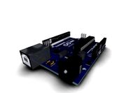
This project started out as a way to take the electronics from underneath my Folgertech Delta printer to mount on the outside like I was doing with just the display. When someone https://www.vicious1.com/forum/topic/mini-rambo-case/#post-39961 asked about a case for the Rambo Mini with Graphics LCD, I decided to make this project more adaptable.
This can be used with either the Arduino mega or the Rambo Mini and the Graphics LCD controller. Here is the controller this was sized for: https://shop.vicious1.com/products/full-graphic-smart-controller-big . You could also use this with other electronics that use this display if you make a base plate to mount it on.
Most of the parts use dovetail joints instead of screws. In the openscad files, you can adjust the clearance of the dovetail joints to .15, .2, .25, .3 or .4. That is the total clearance of the joints, so for .2mm it is .1mm on each of the joint. The stl files I have included us .25mm clearance. You could also add some text to that blank spot on the faceplate. There are example settings for this setup in the openscad file. There is also a test print for the face plates for checking the hole pattern if you are not sure whether your controller is this size. I have checked the 2004 LCD with one I have & it fits & someone else has checked the Graphics LCD. The only problem I heard with the Graphics LCD is the SD card was difficult to get out. I have made that hole larger with an oval outer cutout which might make it easier now.
That file for the LCD2004: TestPrint_LCD2004FacePlate_Rev138.stl
That file for the Graphics controller:TestPrint_GraphicsLCD_FacePlate_Rev138.stl
The holes for that I sized to use the electrical endcaps in this thingiverse design: https://www.thingiverse.com/thing:978384
I took this Full Graphic Smart Controller case & overlaid it on my design to get the SD card cutout. https://www.thingiverse.com/thing:1562144
If you are happy with the test print, the parts you want to print for a stand alone case are:
DD_2_TopCoverPlate_Rev138.stlDD_2_BackPlate_Rev138.stlLCD2004FacePlate_Rev138.stl or GraphicsFacePlate_Rev138.stl
LCD 2004 End CapsDD_2_LCD2004_LeftRightEndCaps_Rev138.stl
or Graphics LCD End CapsDD_2_GraphicsLCD_LeftRightEndCaps_Rev138.stl
The electronics base plates are only 2mm thick, but adjustable to 4.5mm with openscad file.
For the Arduino electronics print:DD_2_ArduinoMount_Rev138.stl
For the Rambo Mini electronics print:DD_2_RamboMiniMount_Rev138.stl
If you are going to mount this case to the side of delta printer like the Folgertech or to a piece of wood, you will have to print the different brackets & back plate:DS_LeftRightBrackets_Rev138.stl
The back plate might be difficult to use in this configuration, but included it.DS_BackPlate_Rev138.stl
There are a lot of parts to keep straight here. Most of the variables in the openscad files are documented. If I have missed something or can explain anything better, just leave a comment.
Someone commented that the Rambo Mini is a little off. Since I do not have a Rambo Mini to check this, someone else will have to tell me the correct dimensions to change this to.
5/7/2018
I updated the openscad file to have a 1.5mm base under the electronics board. It seemed like a better idea to give more protection to the electronics underneath rather than saving a little plastic. The module I added to the openscad code is Bottom_Flat() for those interested in that.
9/9/2017
I added a vented top option for passive heat release. DD_2_TopPlateFullVented_Rev140.stl or DD_4_TopPlateFullVented_Rev140.stl
I also updated the solid top plate version to have less plastic in the middle to cut down on print time. DD_2_TopPlateFullSolid_Rev140.stl or DD_4_TopPlateFullSolid_Rev140.stl
9/7/2017
I am working on another remix to attach the raspberry Pi to the Back or Top along with the Arduino or Rambo and the LCD2004 or LCD Graphics. I am changing the front plate angle from 60 to 75 degrees to give more room on the top plate for the Pi. I also have to add a little to the height & width for a better fit. The raspberry Pi combo can now be found: https://www.thingiverse.com/thing:2525426
8/31/2017
I made some major changes to the openscad file to be able to adjust the angle of the Face plate. You can now adjust that in the customizer from 45 degrees to 90. If you make any changes to the code, you will have to create new STL files of affected parts. I also added a couple of images showing how the variables work for the faceplate cutouts & the electronics mount.
8/25/2017
I changed the openscad source so it will now work with thingiverse Customizer. That should make it a lot easier for others to use that are not familiar with openscad. I have deleted all of the previous versions of the files.
There are quite a few variables you can adjust. Before you get carried away & print all the parts, I would 1st print:
DD_2_TestPrints_Rev138.stl
and DD_LeftRightBrackets_Rev138.stl.
DD types have dovetail backs & the DS types have holes for mounting to frame like a Delta printer.
The brackets have the female dovetail joints that do not change, so you will not have to reprint the left bracket if the joints are too loose or too tight.
If the dovetail joints are too tight, try the DD_4. This is a test print of the Left bracket & all the joints that connect to it. You should only need to print the left bracket once since those joints do not change, only the joints that connect to them. If you have to print a 2nd test print, You can also use the left bracket you printed for your final parts.DD_2_TestPrints_Rev138.stl .25mm toleranceDD_4_TestPrints_Rev138.stl .4mm tolerance
Since I do not have a Rambo Mini or the graphics controller yet, this has not been completely tested yet. I tested the 2004 LCD with one I have & it lines up good. Someone tested the lining up of the graphics faceplate. The only problem reported was access to the SD card was difficult. I made that opening with an oval cutout which should make it easier now.
This project started out as a way to take the electronics from underneath my Folgertech Delta printer to mount on the outside like I was doing with just the display. When someone https://www.vicious1.com/forum/topic/mini-rambo-case/#post-39961 asked about a case for the Rambo Mini with Graphics LCD, I decided to make this project more adaptable.
This can be used with either the Arduino mega or the Rambo Mini and the Graphics LCD controller. Here is the controller this was sized for: https://shop.vicious1.com/products/full-graphic-smart-controller-big . You could also use this with other electronics that use this display if you make a base plate to mount it on.
Most of the parts use dovetail joints instead of screws. In the openscad files, you can adjust the clearance of the dovetail joints to .15, .2, .25, .3 or .4. That is the total clearance of the joints, so for .2mm it is .1mm on each of the joint. The stl files I have included us .25mm clearance. You could also add some text to that blank spot on the faceplate. There are example settings for this setup in the openscad file. There is also a test print for the face plates for checking the hole pattern if you are not sure whether your controller is this size. I have checked the 2004 LCD with one I have & it fits & someone else has checked the Graphics LCD. The only problem I heard with the Graphics LCD is the SD card was difficult to get out. I have made that hole larger with an oval outer cutout which might make it easier now.
That file for the LCD2004: TestPrint_LCD2004FacePlate_Rev138.stl
That file for the Graphics controller:TestPrint_GraphicsLCD_FacePlate_Rev138.stl
The holes for that I sized to use the electrical endcaps in this thingiverse design: https://www.thingiverse.com/thing:978384
I took this Full Graphic Smart Controller case & overlaid it on my design to get the SD card cutout. https://www.thingiverse.com/thing:1562144
If you are happy with the test print, the parts you want to print for a stand alone case are:
DD_2_TopCoverPlate_Rev138.stlDD_2_BackPlate_Rev138.stlLCD2004FacePlate_Rev138.stl or GraphicsFacePlate_Rev138.stl
LCD 2004 End CapsDD_2_LCD2004_LeftRightEndCaps_Rev138.stl
or Graphics LCD End CapsDD_2_GraphicsLCD_LeftRightEndCaps_Rev138.stl
The electronics base plates are only 2mm thick, but adjustable to 4.5mm with openscad file.
For the Arduino electronics print:DD_2_ArduinoMount_Rev138.stl
For the Rambo Mini electronics print:DD_2_RamboMiniMount_Rev138.stl
If you are going to mount this case to the side of delta printer like the Folgertech or to a piece of wood, you will have to print the different brackets & back plate:DS_LeftRightBrackets_Rev138.stl
The back plate might be difficult to use in this configuration, but included it.DS_BackPlate_Rev138.stl
There are a lot of parts to keep straight here. Most of the variables in the openscad files are documented. If I have missed something or can explain anything better, just leave a comment.
Similar models
thingiverse
free

Pi & Arduino Mega or Rambo Mini & LCD2004 or LCD Graphic Controller Case by GeoDave
...ange. i did print all the files from the previous design and they fit well for me.
if i have missed any files here, let me know.
thingiverse
free

Pi & MKS Gen 1.4 & LCD2004 Controller Case by GeoDave
... face plate. the shims go between the bracket & lcd mount on the one side. i include stl files for 1mm, 3mm, 7mm & 8mm.
thingiverse
free

FT5 Full Graphic Controller Angeled Mount by FireBookDuo
...
all stl files have been repaired, oriented and are ready to print.
this could also work on other 2020 extrusion framed printers.
thingiverse
free

Raspberry Pi Electronics Enclosure with Arduino Mega or Rambo Mini and 7" HDMI TouchScreen Display by GeoDave
...ch should barely fit on an 8" print bed.
for further info on this design, refer to https://www.thingiverse.com/thing:2466915
thingiverse
free

LCD Panel Face Plate & Bracket for Folger Tech Kossel 2020 by GeoDave
...ign.
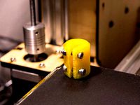
i printed these parts at 20% infill in yellow petg. i added enough photos that should show you how to assemble these parts.
thingiverse
free

LCD Controller Mount for Prusa i3 6mm frame by AndrewBCN
...iginal author(s) for the parts that have been remixed (unfortunately only the .stl files are available for the lcd2004 brackets).
thingiverse
free

Reprap discount full graphic controller mount Lulzbot Mini v1.03 by nsalois
... off, and made one cut in the new one so there was no need to un-wire my mini rambo.
this does not work for the newer mini v1.04.
thingiverse
free

Case for LCD smart controller by gergap
...rces are available also on github: https://github.com/gergap/lcd_case
todo: add reset button. at the moment it don't need it.
thingiverse
free

Full graphic LCD controller holder by Ben_Dps
...you want to change this.
you just have to print the part and its symmetry. you will need 2 wood screws.
of course, print it flat.
thingiverse
free

Arduino and SainSmart LCD control housing by courtjester22
...the housing to hold the arduino in the housing. one image shows the supports that were printed for the lcd perimeter protrusion.
Geodave
thingiverse
free
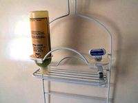
Shower Caddy accessory holder by GeoDave
... upside down on out shower caddy. i did this a few months back, but changed the design recently to make it stay in place better.
thingiverse
free
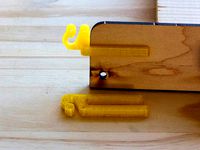
Wood Bracket with Wire Clip by GeoDave
...be either at 0 or 90 degrees to wood bracket. i included the openscad & dxf files if you want to adjust this to other sizes.
thingiverse
free
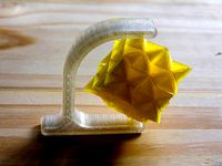
Gimbal Spinner by GeoDave
...elow 24mm for the inside width clearance distance or below 54mm for the gimbal distance. i will take a look at fixing that soon.
thingiverse
free
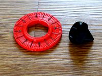
Spinning Top with Thumbwheel by GeoDave
... works.
https://youtu.be/fpaissfvmqm
here is the openscad source file for the thumbwheelhttps://www.thingiverse.com/thing:2407027
thingiverse
free
Parametric Shaft Coupler by GeoDave
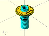
... - m3x14mm bolts & locknuts for the 5mm to 5mm that is shown printed in yellow petg.
you can also open this in the customizer
thingiverse
free
Thumbwheel for a Jack Screw by GeoDave
...ese parts, i realized this might make a good spinning top. here is a link to that top. https://www.thingiverse.com/thing:2407034
thingiverse
free
Remix of Meade Autostar holder for LXD75/LX90 mount by GeoDave
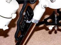
... added 1mm extra around the holes.
i used 2 - m3x16mm screws with locknuts & printed at 40% infill with esun silver pla pro.
thingiverse
free
Parametric Tapered Spacer by GeoDave
... the larger diameter against the wheels & they did not roll at all. the 2nd & 3rd photo should show what i mean by this.
thingiverse
free
A Very Customizable Funnel by GeoDave
...gs in the openscad script.
i changed the hook_xx variable names to a more appropriate eye_xx names after a friend mentioned this.
thingiverse
free
Parametric Honeycomb containers by GeoDave
...file to varie the size of them based on 8 variables. since making this, i have made a number of containers for various purposes.
Rambo
3d_export
$6

rambo knifle
...rambo knifle
3dexport
rambo knifle
turbosquid
$15

Rambo kids
...ree 3d model rambo kids for download as ma, obj, fbx, and stl on turbosquid: 3d models for games, architecture, videos. (1296184)
turbosquid
$11

Rambo KNIFE
... available on turbo squid, the world's leading provider of digital 3d models for visualization, films, television, and games.
3d_export
free

knife rambo
...knife rambo
3dexport
subscribe to my youtube channel:
3d_export
$15

Rambo knife 3D Model
...rambo knife 3d model
3dexport
knife rambo military melee army weapon
rambo knife 3d model anton9421942322 94089 3dexport
3d_export
$10

Rambo Bowie Knife 3D Model
...o bowie knife 3d model
3dexport
rambo bowie knife first blood weapon blade
rambo bowie knife 3d model masterkirkby 38503 3dexport
3ddd
$1

игровой автомат "Rambo"
...ой автомат "rambo"
3ddd
игровой автомат
игровой автомат "рэмбо"... моделил по фото, размеры учтены...
3d_export
$6

bowie knife
...textures and good polygon loading (highpoly), based on the rambo movie. it consists of 3 fundamental parts: blade, handle...
3d_export
$10

Kitchen knife 3D Model
...kitchen knife 3d model 3dexport rambo knife knifes blade old wooden weapon stab cut switchblade...
3d_export
$15

Classic knife 3D Model
...classic knife 3d model 3dexport tactical rambo knife knifes blade old wooden weapon stab cut switchblade...
2004
3ddd
$1

Stilema 2004
...stilema 2004
3ddd
stilema , тумба
тумба под tv stilema 2004
размер: 161х52х69 см
turbosquid
$30

2004.max
... available on turbo squid, the world's leading provider of digital 3d models for visualization, films, television, and games.
3d_export
$25

Dacia Logan 2004
...dacia logan 2004
3dexport
3d model dacia logan 2004 file. max2016 - fbx - obj polys. 39 104 verts. 36 046
3d_export
$60

Jaguar xj8 2004 3D Model
...jaguar xj8 2004 3d model
3dexport
jaguar xj8 2004
jaguar xj8 2004 3d model rustamm 337 3dexport
3ddd
$1

Audi RSQ Concept 2004
...audi rsq concept 2004
3ddd
audi rsq concept 2004 из фильма я робот.
без текстур
turbosquid
$119

Koenigsegg CCR 2004
... available on turbo squid, the world's leading provider of digital 3d models for visualization, films, television, and games.
turbosquid
$40

opel astra 2004
... available on turbo squid, the world's leading provider of digital 3d models for visualization, films, television, and games.
3d_export
$69

2004 Pontiac Vibe 3D Model
...pontiac vibe 3d model
3dexport
2004 pontiac vibe car vehicle automobile van
2004 pontiac vibe 3d model kreations3d 42559 3dexport
3d_export
$29

Toyota Avalon 2004 3D Model
...oyota avalon 2004 3d model
3dexport
toyota avalon 2002 2003 2004 2005 cars
toyota avalon 2004 3d model 3dlogicline 39543 3dexport
3d_export
$29

Kia Spectra 2004 3D Model
...kia spectra 2004 3d model
3dexport
kia spectra 2002 2003 2004 2005 cars
kia spectra 2004 3d model 3dlogicline 39537 3dexport
Mega
3ddd
$1
BoConcept / Mega
...boconcept / mega
3ddd
boconcept
boconcept mega
3ddd
free
Angelo - Mega shoin
... mega shoin , shoin
angelo - mega shoin - 3dmax 2008
3ddd
$1
Комод MEGA
...вана по фото с учетом реальных размеров.
стек не сколапсен, есть возможность регулировки уровня сглаживания.
текстуры в архиве.
3ddd
$1
Hulsta / Mega-design
...hulsta / mega-design
3ddd
hulsta
hulsta mega-design
design_connected
$18
Tolomeo Mega
...
photo-realistic 3d models of the tolomeo mega floor lamps from artemide for 3d architectural and interior design presentations.
turbosquid
$119

Mega Soldier
... free 3d model mega soldier for download as obj, c4d, and fbx on turbosquid: 3d models for games, architecture, videos. (1148568)
turbosquid
$100
Mega Yacht
... free 3d model mega yacht for download as obj, fbx, and blend on turbosquid: 3d models for games, architecture, videos. (1368903)
3ddd
$1
Massproductions Mega
... massproductions , mega
ширина: 180 см
глубина: 90 см
высота: 79 см
3d_export
$4
mega metro station
...mega metro station
3dexport
mega metro station. ready to game. thanks all downloaders!!
3ddd
$1
BAS Mega
...bas mega
3ddd
bas , ванна
ванна
Arduino
turbosquid
$7
Arduino
...turbosquid
royalty free 3d model arduino for download as max on turbosquid: 3d models for games, architecture, videos. (1197165)
turbosquid
$3
Arduino
...turbosquid
royalty free 3d model arduino for download as c4d on turbosquid: 3d models for games, architecture, videos. (1305484)
3d_export
$5
arduino satellite
...rt
this model is the exact arduino based satellite model with some basic sensors and camera modules and also includes batteries.
turbosquid
$1
Arduino UNO
...alty free 3d model arduino uno for download as , stl, and wrl on turbosquid: 3d models for games, architecture, videos. (1515932)
3d_export
$5
esp8266 box arduino
...esp8266 box arduino
3dexport
box for esp8266 module with wire hole. inside dimensions: 49x26 mm. height 15 mm.
3d_export
$60
Arduino Uno Rev3 Microcontroller 3D Model
...mega328p circuit board spark cable wire 5v 74v 9v 111v
arduino uno rev3 microcontroller 3d model danielgarnier4403 97237 3dexport
3d_export
free
arduino rover kit
...no!!! materials: no!!! rigged: no animated: no uv mapped: no it is not an exact copy of the original! not subject to 3d printing!
3d_ocean
$7
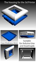
The housing for the 3d Printer
...the housing for the 3d printer 3docean arduino device housing stl the housing consists of two portions:...
3d_export
$5
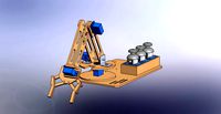
arm 4 axis
...uno -4 servo motor 180° -3 joystick (x,y) for arduino -mdf wood -some wires -cnc laser cut...
3d_export
$5
solar tracker
...machine for the frame . list of material : -arduino uno -2 step motor with driver -4 ldr sensor...
Graphic
3d_export
free

graphic tablet
...graphic tablet
3dexport
graphic interactive table.
3d_export
free

Graphic tablet
...graphic tablet
3dexport
a graphics tablet for your renderers.<br>the archive also has decal files
turbosquid
$30

Graphic Tablet
...d
royalty free 3d model graphic tablet for download as blend on turbosquid: 3d models for games, architecture, videos. (1356300)
turbosquid
$16

Graphics Tablet
... available on turbo squid, the world's leading provider of digital 3d models for visualization, films, television, and games.
turbosquid
$7

Analytics graphic
...analytics graphic for download as max, 3ds, obj, fbx, and dwg on turbosquid: 3d models for games, architecture, videos. (1524423)
turbosquid
$5

Graphic tablet
... available on turbo squid, the world's leading provider of digital 3d models for visualization, films, television, and games.
turbosquid
$5

Graphic Calculator
... available on turbo squid, the world's leading provider of digital 3d models for visualization, films, television, and games.
turbosquid
$5

Graphics tablet
... available on turbo squid, the world's leading provider of digital 3d models for visualization, films, television, and games.
turbosquid
$4

House Graphic
... available on turbo squid, the world's leading provider of digital 3d models for visualization, films, television, and games.
turbosquid
$4

drixtc graphic
... available on turbo squid, the world's leading provider of digital 3d models for visualization, films, television, and games.
Lcd
turbosquid
$20
lcd
... available on turbo squid, the world's leading provider of digital 3d models for visualization, films, television, and games.
turbosquid
$15
LCD
... available on turbo squid, the world's leading provider of digital 3d models for visualization, films, television, and games.
turbosquid
$10
LCD
... available on turbo squid, the world's leading provider of digital 3d models for visualization, films, television, and games.
turbosquid
$10

LCD
... available on turbo squid, the world's leading provider of digital 3d models for visualization, films, television, and games.
turbosquid
$2

lcd
... available on turbo squid, the world's leading provider of digital 3d models for visualization, films, television, and games.
turbosquid
$1
lcd
... available on turbo squid, the world's leading provider of digital 3d models for visualization, films, television, and games.
turbosquid
free

LCD
... available on turbo squid, the world's leading provider of digital 3d models for visualization, films, television, and games.
turbosquid
free
lcd
... available on turbo squid, the world's leading provider of digital 3d models for visualization, films, television, and games.
3ddd
$1
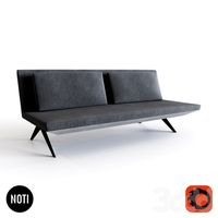
Noti Lcd Sofa
...noti lcd sofa
3ddd
noti , lcd
3d model of noti lcd sofa
3d_ocean
$7

Lcd tube wall
...hrome electronic electronic lcd tv videowall
lcd tube wall you can put in the lcd your own texture or movie in it and animate it.
Enclosure
3d_export
free
electrical enclosure
...l enclosure where electrical devices like (relays, contactors, busbars ) are kept in order to protect from hazardous environment.
turbosquid
$100
GPU Enclosure
...yalty free 3d model gpu enclosure for download as obj and stl on turbosquid: 3d models for games, architecture, videos. (1381061)
3d_export
$5
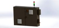
Electrical Enclosure
...ed. also has tower lights attaced on the top.<br>file format that are available:<br>.step<br>.obj<br>.stl
archive3d
free
Enclosure 3D Model
...closure 3d model
archive3d
shower enclosure-acquarius- 3d model for interior 3d visualization.
archive3d
free
Enclosure 3D Model
...enclosure 3d model
archive3d
shower enclosure-omega- 3d model for interior 3d visualization.
archive3d
free
Enclosure 3D Model
...enclosure 3d model
archive3d
shower enclosure-vega - 3d model for interior 3d visualization.
archive3d
free
Enclosure 3D Model
...enclosure 3d model
archive3d
shower enclosure-zenith - 3d model for interior 3d visualization.
turbosquid
$20
shower enclosure
... available on turbo squid, the world's leading provider of digital 3d models for visualization, films, television, and games.
turbosquid
$14
Dumpster Enclosure
... available on turbo squid, the world's leading provider of digital 3d models for visualization, films, television, and games.
turbosquid
$25
3d printer enclosure
... model 3d printer enclosure for download as ipt, skp, and fbx on turbosquid: 3d models for games, architecture, videos. (1634310)
Electronics
turbosquid
$1

electron
...urbosquid
royalty free 3d model electron for download as max on turbosquid: 3d models for games, architecture, videos. (1157488)
turbosquid
$50

electronic
...
royalty free 3d model electronic for download as max and obj on turbosquid: 3d models for games, architecture, videos. (1289427)
turbosquid
$40

Electron
... available on turbo squid, the world's leading provider of digital 3d models for visualization, films, television, and games.
3d_ocean
$8
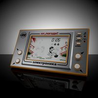
Electronic game
...electronic game
3docean
electronic games nu pogody wait a minute well
electronic game “well, wait a minute”, “nu pogody”
3ddd
$1
Brilux Electronic
...brilux electronic
3ddd
подвес. brilux electronic. польша. материалы настроены.
3d_export
free

electronic shop
...lectronic shop with high quality interior and exterior. it has tvs smartphone play station printer and many more electronic item.
3ddd
$1

Термостаты OJ Electronics
...ермостаты oj electronics
3ddd
oj electronics , термостат
термостаты фирмы oj electronics
3d_export
$8

electron 714
...electron 714
3dexport
game ready model for export to unreal engine soviet tv electron 714 pbr 4k
3ddd
$1
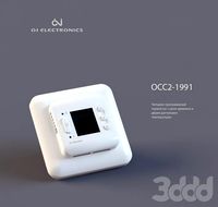
Термостат OJ Electronics
... oj electronics
3ddd
oj electronics , термостат
термостат occ2-1991 фирмы oj electronics
turbosquid
$60
Electronics Stuff
...
royalty free 3d model electronics stuff for download as max on turbosquid: 3d models for games, architecture, videos. (1624680)
Mini
turbosquid
$10
Mini Mini Luceplan
...
royalty free 3d model mini mini luceplan for download as max on turbosquid: 3d models for games, architecture, videos. (1227359)
3d_ocean
$39
Mini Cooper
...mini cooper
3docean
cabrioler cooper mini
mini cooper cabrioler
3d_export
$30

Mini lathe
...mini lathe
3dexport
mini lathe
3d_export
$5

mini mouse
...mini mouse
3dexport
mini mouse
3d_export
$5
mini house
...mini house
3dexport
mini house
3d_export
free

Mini Mecha
...mini mecha
3dexport
concept of mini mecha
3d_ocean
$20
Mini Gun
...mini gun
3docean
gatling gun gun machine gun mini gun weapon
model of a mini gatling gun.
3ddd
free
Herve mini
... кофейный , herve
http://www.mobiliavenanti.it/ru/products/hervè-mini
3d_export
$5
mini wall
...mini wall
3dexport
mini wall for living room
3d_export
$5

mini bank
...mini bank
3dexport
mini bank 3d model
Controller
3d_ocean
$4
Controller TQFP32
...qfp32
3docean
chip controller cpu electronic gpu mcu micro controller silicon smd tqfp wafer
a micro controller in tqfp32 package
3d_ocean
$4
Controller TQFP44
...44
3docean
chip controller cpu electronic gpu mcu micro controller package smd tqfp tqfp44
a micro controller in a tqfp44 package
3d_export
$15
control unit
...control unit
3dexport
control unit
3ddd
$1
Yacht control
...yacht control
3ddd
yacht control
3d_export
$5
controle pgdm
...controle pgdm
3dexport
carcaca controle pgdm
turbosquid
free
controler
... available on turbo squid, the world's leading provider of digital 3d models for visualization, films, television, and games.
3ddd
$1
Control
...
http://www.schmitz-leuchten.de/html-ru/einzelleuchten-lampentyp-details.php?lamptype_no=700&group;=917&id;=731
3d_ocean
$4
Controller TQFP100
...100
3docean
chip computer cpu electronic gpu mcu micro controller pin platine silicon wafer
a micro controller in tqfp100 package
3d_ocean
$4
Controller TQFP64
...qfp64
3docean
chip computer cpu gpu mcu micro controller package silicon tqfp tqfp64 wafer
a micro controller in a tqfp64 package
3d_ocean
$7

Remote controller
... control switcher tv remote
remote controller for tv, sound systems etc easy to edit textures photo real rendered with mental ray