Thingiverse
Electric Skateboard Remote RC by wafflejock
by Thingiverse
Last crawled date: 3 years ago
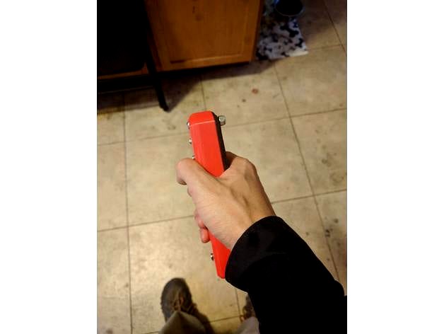
This is an RC controller I designed to go with my electric skateboard. Was previously using a RC car controller but it was excessively bulky and ate a lot of batteries. Designed this one around using an arduino nano and rf module on the transmitter and receiver sides and just wrote some code to read a potentiometer in the transmitter here and sends it along to another one that then uses the servo library to send a signal to the ESC that controls the motor.
1_1 Made trigger a bit longer though it wasn't trouble in use the trigger could slip in the main controller area before, also spread out are where the spring mounts between spring and main controller body. Increased size of cover since it was falling into the bottom section when screwed on. Increased height of main controller body to account for potentiometer height so it doesn't rub on the lid, also increased USB and switch hole sizes to make inserting components easier.
Update 1
Added an image of the wiring, considering getting some PCBs printed to simplify connecting the components since the wiring did end up being a bit of a rats nest. Would be around $10-$15 a piece to get a few made. Uploaded images of the built controller as well. The wiring for the receiver is the same with the exception that the analog (A1) is used on the transmitter to read the position of the potentiometer whereas on the receiver the digital pin D5 (PWM) is used to send the microSecond pulses for controlling the ESC.
If using the code below first turn on the transmitter then sweep the trigger to max and min positions this will calibrate the values used to map the max/minimum it sends to the receiver. Power on the receiver after the calibration is done otherwise you will have a run away vehicle.
Update 2
Didn't note it in the wiring diagram or text before here but good to put an electrolytic capacitor between ground and vin on the arduino (around 100uF ~16V one is working well for me) This was needed on the receiver side or else it seems the VESC's BEC that was giving me the 5V to run the arduino would occasionally dip when the motor was drawing a lot of power and the dip was enough for some part of the arduino to brown out. Since adding the capacitor between ground and Vin (make sure polarity is correct) the LEDs shine bright and it hasn't browned out again yet (biggest problem I had since was loose connections between receiver and ESC but soldered those on and has been a solid connection for the last few days).
On a more positive note the controller lasts forever on a charge. In wanting to verify the charger was working after installing the guts in a new print and took a good hour before the voltage had even dipped enough for the charger to not consider it 100% full (I checked with a voltmeter as well and was sitting around 4.14V), so super happy with the efficiency of the whole thing even without any tuning in that regard.
Update 3 https://github.com/shusain/eskatecontroller Posting further updates for the Arduino code and Eagle files for making PCBs to connect the Arduino (pro mini 3.3V) to the nordic RF modules. Found using Arduino Nano I was getting drop outs on the receiver side occasionally (possibly due to fluctuations in em interference on the 5V supply, but seems stable so far with 3.3V). The PCB design is exported as pcb.png in the eagle folder for a single sided DIY at home PCB.
Update 4
Adding a box used for the receiver on the board, also updated the PNG in the linked github repo for at PCB making to work for both the controller and receiver and use a servo style JST plug where the power is in the center and ground is on the edge to avoid accidental reversing the polarity (not that I did that).
Update 5
Working on a new version of this using parametric CAD software to make it easier to tweak the design and refine it. Ordered PCBs from pcbway, was $28 for 10 boards delivered (slight discount for first order) they were of acceptable quality to me and have worked well for the last 6 months or so.
https://cad.onshape.com/documents/50e9e32d777391df91fbe5a9/w/19598faab2182f3b574dcfaf/e/52a747c0c2e141ee735a22b8
Update 6
Added new images and STL files for the onshape based one with the new custom PCBs. 4 new STL files for the controller (all start with RC Controller - )
Update 7
Added a V2 of the controller requires M3 screws of various sizes (will get measurements soon to fill in here but just had a mixed kit) and a few M3 nuts to hold the new "idle arm" in place to properly pull the trigger back to idle reliably. Also used a hall sensor in the new version of the remote and a magnet in the trigger to sense the position of the trigger relative to the hall sensor, this worked amazingly well, I also set a midpoint in the new source code and will update on github shortly.
https://photos.app.goo.gl/C1tx6fe2DGsTn1M8A
Similar models
thingiverse
free

CARduino controller: Arduino based rc car radio transmitter
...ack plate)
-3x tiny screws to mount pcb on back plate.
i uploaded my arduino codes (transmitter and receiver) with the stl files.
thingiverse
free

Custom Trigger for Flysky FS-GT3B Transmitter by TheMetalikMelon
...ler for an airboat with an airplane esc. if you have an application with an airplane esc on an r/c car or boat this mod is great!
grabcad
free

RC - PLANE model (CONCEPTUAL)
...rfaces based on the position of joysticks on the transmitter. the control surfaces, in turn, affect the orientation of the plane.
thingiverse
free

Minuture RC Controler by KyungSun
...i used these ones here: http://amzn.com/b00dn7msxy
the rubber bands are used to return the controls to the centered/off position.
cg_trader
$5

Rc Aircraft Design | 3D
...rfaces based on the position of joysticks on the transmitter. the control surfaces, in turn, affect the orientation of the plane.
grabcad
free

Quadcopter
...ds rc transmitter with fs-ia6 receiver modules are used. other parts used in the project are modules that can be easily obtained.
thingiverse
free

Arduino Volume Control by xicocana
...to change between speakers and headset.
parts used:
arduino nano
potentiometer
2 state switch
100k resistor for the switch
wires
3dwarehouse
free

Connector 6 pins 90 degrees for PCB
...0 degrees for pcb
3dwarehouse
connector used for connecting cables to pcb. works very well for arduino. #arduino #connector #pcb
grabcad
free

Wireless Radio Transmitter and Receiver nRF24L01
...radio transmitter and receiver with the arduino and nrf library to connect with other arduinos or devices such as rpi wirelessly.
thingiverse
free

Arduino Nano RC Transmitter by AlxUta
...
two joysticks
two potentiometers
two toggle switches
six buttons ( two from the joysticks )
accelerometer and a gyroscope sensor
Wafflejock
thingiverse
free

VESC4 and receiver enclosure by wafflejock
...ure by wafflejock
thingiverse
just a box for the vesc4 with a place for the receiver to mount and a spot for a bluetooth module.
thingiverse
free

Quadcopter LED holder by wafflejock
...rew onto two 30mm spaced 3mm screws (on front or back of 250mm quadcopter) and holds leds on the front and back for illumination.
thingiverse
free

250 Quad Copter Leg by wafflejock
...an fit on a 250 quadcopter arm and can be held on with a zip tie. wanted something simple that could be molded relatively easily
thingiverse
free

Thumbstick/Joystick Cover by wafflejock
...ex. i imagine they will fit other controllers as well basically just caps for the little plastic hat on the top of the joystick.
thingiverse
free

VESC Case mod by wafflejock
...n the vesc and the capacitors also put a hole in for the servo jst to be exposed since i'm using that for my custom receiver.
thingiverse
free

RunCam Split 2 quadcopter mount by wafflejock
...atch the size of the aluminum 'stand-offs' i'm using and two options of either 35 degree or 45 degree camera up tilt.
thingiverse
free

Skate Riser Lights by wafflejock
...igh infill 50% or more if you plan to just use the 3d printed versions, tried with pla but it breaks down eventually and cracks).
thingiverse
free

Peon230 HD camera mount by wafflejock
...pdated file is the _2 version has the parts to avoid needing to buy extra mount parts, can slide the go pro right on top of this.
thingiverse
free

E3D v6 X Carriage Minimal by wafflejock
...
uses 2 m4 screws and nuts, 30mm in length or longer.
update
added a version 2 that includes parts for having a part cooling fan.
thingiverse
free

E-Skateboard LiPo battery holder (enclosure) by wafflejock
...board.
update added the new design with the battery trays that can slide out.
related to:http://www.thingiverse.com/thing:1864536
Skateboard
3d_ocean
$9

Skateboard
...skateboard
3docean
board materials skate skateboard skateboarding sport
highly detailed skateboard.
3d_ocean
$5

skateboard
...skateboard
3docean
skateboard sports
skateboard 3d
3d_ocean
$5

Skateboard
...skateboard
3docean
skateboard
skateboard model .obj and .ma
3d_ocean
$5

Skateboard
...skateboard
3docean
skateboard
a high quality skateboard which is ready to use in game
3d_ocean
$15

Skateboard
...y – lighting, vray – materials files included: - .max – scene and skateboard models, lightening - .obj - .fbx - .3ds - .materials
3d_ocean
$15

Skateboard
...cks
3d model of skateboard .objects are grouped.rendering scene with texture,materials are included and detailed, with all files.
3ddd
$1

SoulArc Skateboards
...soularc skateboards
3ddd
soularc skateboards , скейт
soularc skateboards
turbosquid
free

Skateboard
...rd
turbosquid
free 3d model skateboard for download as blend on turbosquid: 3d models for games, architecture, videos. (1290376)
turbosquid
$39

Skateboard
...bosquid
royalty free 3d model skateboard for download as max on turbosquid: 3d models for games, architecture, videos. (1605988)
turbosquid
$25

skateboard
...bosquid
royalty free 3d model skateboard for download as c4d on turbosquid: 3d models for games, architecture, videos. (1483231)
Remote
archibase_planet
free

Remote
...remote
archibase planet
tv remote remote controller remote
remote - 3d model for interior 3d visualization.
archibase_planet
free

Remote
...e
archibase planet
remote control remote controller remote
remote n140512 - 3d model (*.gsm+*.3ds) for interior 3d visualization.
turbosquid
$1

Remote
...
turbosquid
royalty free 3d model remote for download as obj on turbosquid: 3d models for games, architecture, videos. (1487515)
3d_export
$5
Tv Remote
...tv remote
3dexport
tv remote
3d_ocean
$7

Remote controller
... control switcher tv remote
remote controller for tv, sound systems etc easy to edit textures photo real rendered with mental ray
turbosquid
$39

remote
...free 3d model remote for download as obj, fbx, blend, and dae on turbosquid: 3d models for games, architecture, videos. (1387531)
turbosquid
$5

remote
...free 3d model remote for download as 3ds, obj, fbx, and blend on turbosquid: 3d models for games, architecture, videos. (1401849)
archive3d
free
Remote 3D Model
...l
archive3d
tv remote remote controller remote
remote - 3d model for interior 3d visualization.
turbosquid
$11
Remote
... available on turbo squid, the world's leading provider of digital 3d models for visualization, films, television, and games.
turbosquid
$10

remote
... available on turbo squid, the world's leading provider of digital 3d models for visualization, films, television, and games.
Rc
3ddd
$1
RC Helicopter
...rc helicopter
3ddd
вертолет
mini rc helicopter
93.329 polys
3d_export
$7
rc helicopter model
...rc helicopter model
3dexport
rc helicopter model
3d_ocean
$25
RC F1
...rc f1
3docean
auto car control f1 formula race rc remote speed
remote control f1 car
turbosquid
$10
rc plane
...lane
turbosquid
free 3d model rc plane for download as blend on turbosquid: 3d models for games, architecture, videos. (1295828)
turbosquid
$100
RC Helicopter
...free 3d model rc helicopter for download as 3ds, max, and obj on turbosquid: 3d models for games, architecture, videos. (1298511)
turbosquid
$59

Drone with RC
...3d model drone with rc for download as 3ds, max, obj, and fbx on turbosquid: 3d models for games, architecture, videos. (1363601)
turbosquid
$75
RC buggy
... available on turbo squid, the world's leading provider of digital 3d models for visualization, films, television, and games.
turbosquid
$39

RC Plane001
... available on turbo squid, the world's leading provider of digital 3d models for visualization, films, television, and games.
turbosquid
$30
RC Jet
... available on turbo squid, the world's leading provider of digital 3d models for visualization, films, television, and games.
turbosquid
$30
Rc airplane
... available on turbo squid, the world's leading provider of digital 3d models for visualization, films, television, and games.
Electric
3d_export
$5

Electric pole
...electric pole
3dexport
electric pole for street, electricity line
3ddd
$1
electric mixer
...electric mixer
3ddd
electric mixer , миксер
electric mixer
3ddd
$1
electrical installation
...electrical installation
3ddd
electrical installation , розетка
electrical installation
turbosquid
$19
The electric water heater electric
... available on turbo squid, the world's leading provider of digital 3d models for visualization, films, television, and games.
turbosquid
free
Electrical Outlet electric splitter
... available on turbo squid, the world's leading provider of digital 3d models for visualization, films, television, and games.
3d_ocean
$20
Electric Guitar
...electric guitar
3docean
electric electric guitar guitar music music instrument
model of a electric guitar created in maya.
3d_ocean
$12
Electric Shaver
...electric shaver
3docean
electric electric shaver hair removal personal care shaver shaving
electric shaver created in 3ds max.
3ddd
$1
electrical switch
...h
3ddd
electrical , розетка
electrical switch from bticino company
series livinglight
3d_export
$7
Electric Conveyor
...electric conveyor
3dexport
electric conveyor
3d_export
$5
electric drums
...electric drums
3dexport
electric drums