Thingiverse

Ekobots - Perpetual motion motor by jsirgado
by Thingiverse
Last crawled date: 3 years ago
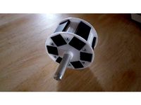
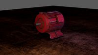
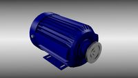
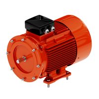
Perpetual motion motor, magnetic shield engine.
Holiday, Brazil, sunny day...
Let's build a perpetual motion engine.
Different of all perpetual motion engines that you can find in the internet,THIS ONE DOES NOT WORK, yet. But that is just a little detail. ;-P
You can try another arrangement for the magnets, who knows...
I know all physics and thermodynamics laws,
and know this object goes against me, but I did it, why not?
All you need:
5x bearing (13 x 5 x 4 mm)
2 for the shield frame, 2 for motor frame, 1 for 18 teeth gear;
2x screw (60 x 4 mm) for motor frame;
1x screw (20 x 4 mm) for 18 teeth gear;
1x threaded rod (120 x 4mm) or screw full threaded for shaft;
10x cylinder magnetic (6 x 5 mm) for the rotor;
12x rectangular magnetic (10 x 10 x 3 mm) for the stator;
2x mild steel plate (20 x 20 x 2.5 mm) for the magnetic shield,
or an old hard disk to remove and cut the magnetic shielding
or other material with properties to block the magnetic field.
some nuts and washers for (4 mm) screw;
Simulation video:http://www.youtube.com/watch?v=LyJRjkUYaVE
Assembly sequence:
1 - Clean all parts;
2 - Use small washers or pieces of plastic pipe to adjust the position of all parts
in the shaft;
3 - Fix the magnets in the rotor, you can use glue or adhesive tape;
4 - Fix the magnets in the stator, you can use glue or adhesive tape;
5 - Fix the rotor near the center of the shaft with 2 nuts and 2 washers and make
sure it is really well fixed;
6 - Fix 2 bearings in the shield frame;
7 - Fix 2 bearings in the shield motor;
8 - Fix 1 bearing in the 18 teeth gear;
9 - Use 2 pieces of filament 3mm to adjust the 24 teeth shield gear over the shield
frame and glue all;
10 - Insert the 2 parts of the shield frame in the shaft with the rotor in the center and
glue them;
11 - Glue the mild steel plates inside the shield frame;
12 - Mount the motor frame with the rotor and the shield in it using screws, washers
and nuts;
13 - Mount the 18 teeth gear in the motor frame using the small screw, nut and washer;
14 - Fix the 24 teeth rotor gear in the shaft with 2 nuts and 2 washers;
How it should work:
Same as electric motor, you have magnetic fields in the rotor and in the stator.
But the main idea is use the magnetic shield to "turn off" the power,
like in the electric motor the shield cuts the rotor magnetic field,
just at determined positions.
Because we have 2 full rings of magnets the shield can rotate almost "free",
just some diamagnetic effect force.
In the correct position the rotor will be attracted and in all others positions repulsed.
The shield prevent the stop of the rotor when facing the opposite magnetic field in the stator.
The inertial movement will do the job, until the next position of attraction.
Maybe you cannot see, but:
There are a lot of variables, like size, number and position of magnets,
to keep rotor and shield spinning "free", and we can add some improvements
like Hallbach arrangement, curved shield, active magnetically shield, etc.
See the images for the magnets arrangement.
See the "Make" for more tips: http://www.thingiverse.com/make:224114
Use small washers or plastic pipe to adjust the rotor position.
That is all Folks!
Similar models
grabcad
free

Motor with magnetic perpetual motion
...agnets. i can control the revolutions of the engine by moving the two magnets next to the engine and moving them near the engine.
cg_trader
$10

Power Generator | 3D
...d m10 washer at the inside of the rotor, put in stator assembly, add m10 washer and nut to tighten, add power cables to contacts.
grabcad
free

Electromagnetic Motor Design
...gnetic induction to create magnetic field interactions between the rotor and stator, which generates torque and rotational speed.
thingiverse
free

Compact extruder for Prusa i3 and 42YF22GN050R (2engineers) geared motor with shaft support by denisc
... ...300
#define default_retract_acceleration 300
update 13-sep-2014
added long screws, springs, washers, nuts for idler.
thingiverse
free

BLDC motor
...ngs and a 1/4" shaft with a few 1/4" shaft spacers and a locking nut and shaft collar. printed with a longer orange 10.
grabcad
free

Exhaust Fan For Cooler
...netic field may be produced by permanent magnets, reluctance saliency, or dc or ac electrical windings.mechanism is also uploaded
grabcad
free

AC-Motor
...electrical windings. less common, ac linear motors operate on similar principles as rotating motors but have their stationary and...
grabcad
free

WEG AC MOTOR 7.5 HP
...o produce a rotating magnetic field, and an inside rotor attached to the output shaft producing a second rotating magnetic field.
3dwarehouse
free

perpetual motion permanent magnet motor
...nd rotation much like a callaway v-gate motor........the more rotors used the tighter the index and more powerful #concept #motor
thingiverse
free
Permanent Magnet Motor/Generator Rotor by Cotton80
...e. i like gorilla glue. it seems to handle shock and vibration the best. make sure you use water or it won't set properly.
Jsirgado
thingiverse
free

Ekobots - Dice 20mm by jsirgado
...gs like this.
buy my designs at pinshape:http://pinshape.com/users/27920-jsirgado
the openscad file is there, you can change all.
thingiverse
free

Ekobots - Domino by jsirgado
...gs like this.
buy my designs at pinshape:http://pinshape.com/users/27920-jsirgado
the openscad file is there, you can change all.
thingiverse
free

Ekobots - Chess Set by jsirgado
...gs like this.
buy my designs at pinshape:http://pinshape.com/users/27920-jsirgado
the openscad file is there, you can change all.
thingiverse
free

Ekobots - Belt tensioner by jsirgado
...gs like this.
buy my designs at pinshape:http://pinshape.com/users/27920-jsirgado
the openscad file is there, you can change all.
thingiverse
free

Ekobots - Quadcopter frame. by jsirgado
...gs like this.
buy my designs at pinshape:http://pinshape.com/users/27920-jsirgado
the openscad file is there, you can change all.
thingiverse
free

Ekobots - Tire generator. by jsirgado
...gs like this.
buy my designs at pinshape:http://pinshape.com/users/27920-jsirgado
the openscad file is there, you can change all.
thingiverse
free

Ekobots - Tablet base. by jsirgado
...gs like this.
buy my designs at pinshape:http://pinshape.com/users/27920-jsirgado
the openscad file is there, you can change all.
thingiverse
free

Ekobots - Motor cooler. by jsirgado
...gs like this.
buy my designs at pinshape:http://pinshape.com/users/27920-jsirgado
the openscad file is there, you can change all.
thingiverse
free

Ekobots - Mauá emblem. by jsirgado
...gs like this.
buy my designs at pinshape:http://pinshape.com/users/27920-jsirgado
the openscad file is there, you can change all.
thingiverse
free

Ekobots - The sphere in cube. by jsirgado
...gs like this.
buy my designs at pinshape:http://pinshape.com/users/27920-jsirgado
the openscad file is there, you can change all.
Ekobots
thingiverse
free

Bed Shelf bracket for Ekobots - Box-H 3D Printer. by otiki
...bed shelf bracket for ekobots - box-h 3d printer. by otiki
thingiverse
bed shelf bracket for ekobots - box-h 3d printer.
thingiverse
free
Ekobots - Dice 20mm by jsirgado
...gs like this.
buy my designs at pinshape:http://pinshape.com/users/27920-jsirgado
the openscad file is there, you can change all.
thingiverse
free

Ekobots - Fidget Spinner by jsirgado
...gs like this.
buy my designs at pinshape:http://pinshape.com/users/27920-jsirgado
the openscad file is there, you can change all.
thingiverse
free
Ekobots - Domino by jsirgado
...gs like this.
buy my designs at pinshape:http://pinshape.com/users/27920-jsirgado
the openscad file is there, you can change all.
thingiverse
free

My Customized cC - Ekobots - Storage Drawer
...ttp://www.thingiverse.com/thing:866603
created with customizer! http://www.thingiverse.com/apps/customizer/run?thing_id=866603
thingiverse
free
Ekobots - Chess Set by jsirgado
...gs like this.
buy my designs at pinshape:http://pinshape.com/users/27920-jsirgado
the openscad file is there, you can change all.
thingiverse
free
Ekobots - Belt tensioner by jsirgado
...gs like this.
buy my designs at pinshape:http://pinshape.com/users/27920-jsirgado
the openscad file is there, you can change all.
thingiverse
free
Ekobots - Quadcopter frame. by jsirgado
...gs like this.
buy my designs at pinshape:http://pinshape.com/users/27920-jsirgado
the openscad file is there, you can change all.
thingiverse
free
Ekobots - Tire generator. by jsirgado
...gs like this.
buy my designs at pinshape:http://pinshape.com/users/27920-jsirgado
the openscad file is there, you can change all.
thingiverse
free
Ekobots - Tablet base. by jsirgado
...gs like this.
buy my designs at pinshape:http://pinshape.com/users/27920-jsirgado
the openscad file is there, you can change all.
Perpetual
3d_ocean
$5

low poly perpetual motion model
...chnology
low poly perpetual motion model available in the obj format. this model is suitable for decoration. available in 1 model
3d_ocean
$15

Danese Milano Timor perpetual calendar
...nzo mari, 1967. the model is perfect for close ups and detail shots. it has the same movable data cards as the real calendar. ...
3d_export
$15

Danese Milano Timor perpetual calendar 3D Model
...ry modern living italian modelplusmodel model+model
danese milano timor perpetual calendar 3d model modelplusmodel 25510 3dexport
3ddd
$1

Мужские часы Vacheron Constantin Patrimony Traditionnelle Chronograph Perpetual Calendar
... внутри корпуса установлен механизм с ручным заводом, калибр 1141 qp, обеспечивающий запас хода 45 часов.
материалы присутствуют.
3d_export
$11

Rolex Daytona 3D Model
...rolex daytona 3d model 3dexport watches rolex oyster perpetual cosmograph daytona time rolex daytona 3d model x-h3ad 28761...
3d_export
$69

Rolex Submariner 116610 3D Model
...expensive royal rolex submariner 116010 wrist watch automatic oyster perpetual date swiss clock rolex submariner 116610 3d model squir...
3d_export
$69

Rolex Daytona Mens Watch 3D Model
...luxury expensive royal daytona rolex wrist watch automatic oyster perpetual date swiss clock chrono chronometer rolex daytona mens watch...
3d_export
$10

Kids Mobile 3D Model
...3d model 3dexport kids kid baby infant toy cloudlet perpetual motion machine mobile room decoration wind play hobby bed...
3d_ocean
$3

Newtons cradle Pendulum
...cradle fun game lights newton newtons newtons cradle pendulum perpetual realistic science scientific silver stand toy newtons cradle pendulum...
evermotion
$595

Maxwell Render Suite v3 - Node Locked
...product is available only for polish customers. node-locked version perpetual license that can be installed on both your workstation...
Motion
3ddd
$1

Fabbian Motion
...motion
3ddd
fabbian , motion
светильник fabbian коллекция motion. текстурка в комплекте.
design_connected
$7

Motion Notion
...motion notion
designconnected
howard miller motion notion computer generated 3d model. designed by nelson, george.
turbosquid
$10

motion shark
...squid
royalty free 3d model motion shark for download as rib on turbosquid: 3d models for games, architecture, videos. (1261380)
3d_ocean
$6

Motion Set
...ng face and vertex, three file format are included,very useful for motion graphic artist , total poly 143.952 total vertex 79.952
3d_export
$10

Motion Tracker Aliens
...er out moving objects from stationary background and then displayed them on the monitor as a series of contours of probable loci.
3d_export
$6

motion stand for book and logo
...motion stand for book and logo
3dexport
motion stand for book and logo
turbosquid
$99

Planes of Motion Combo
... available on turbo squid, the world's leading provider of digital 3d models for visualization, films, television, and games.
turbosquid
$50

Rotary-straight motion
...y-straight motion for download as 3ds, obj, fbx, 3dm, and skp on turbosquid: 3d models for games, architecture, videos. (1402602)
3d_export
$6

Reciprocating Motion
...#39;vinci's reciprocating motion contraption the model is used for picking up buckets of water from a well materials included
3d_export
$15

M314 Motion Tracker Aliens
...ng objects from stationary background and then displayed them on the m314's monitor as a series of contours of probable loci.
Motor
archibase_planet
free
Motor
...base planet
motor motor engine engine electric motor
motor wagner n250213 - 3d model (*.gsm+*.3ds) for interior 3d visualization.
archibase_planet
free
Motor
...motor
archibase planet
motor motor engine engine
motor n151112 - 3d model (*.gsm+*.3ds) for interior 3d visualization.
archibase_planet
free
Motor
...motor
archibase planet
motor motor engine engine
motor n150615 - 3d model (*.gsm+*.3ds+*.max) for interior 3d visualization.
turbosquid
$15
Motor
...otor
turbosquid
royalty free 3d model motor for download as on turbosquid: 3d models for games, architecture, videos. (1639404)
3d_ocean
$5
Electric motor
...electric motor
3docean
car electric engine industry motor phase train vehicle
an electric motor enjoy!
3d_ocean
$18
Electric Motor
...electric motor
3docean
electric motor engine machine mover parts
3d model electric motor for hoist crane
turbosquid
$29

Motor
... available on turbo squid, the world's leading provider of digital 3d models for visualization, films, television, and games.
turbosquid
$5
Motor
... available on turbo squid, the world's leading provider of digital 3d models for visualization, films, television, and games.
3d_export
$5
electric motor
...electric motor
3dexport
electric motor use for industrial purposes
3d_export
$5

servo motor
...tor
3dexport
it's a simple part of servo motor 0.75kw for used in machines assembly to show specified motor in own project.