Thingiverse
Eggfinder LCD Receiver Case by amiliv
by Thingiverse
Last crawled date: 2 years, 11 months ago
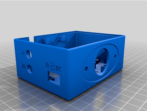
I was unhappy with the placement of GPS module in the Blackaero case, because it had very poor visibility of the sky. So decided to make my own with a bunch of other updates and upgrades. Slowly but surely, it resulted in a design that looks similar on the outside, but completely new design on the inside.
First word of caution. Building this case will be more expensive than simply buying Blackaero case of the shelf. If you do not have optional GPS module and/or have a friend happy with their existing case, buying Blackaero case is much cheaper alternative.
With that out of way, extra materials needed with approximate prices:
ZF On/Off rocker switch: part# PRK22J5DBBNN (around a $1.10)
NKK momentary switch, non-illuminated, red cap: part# HB15CKW01-C (around $8.30 at Mouser/Digikey)
NKK latching switch, non-illuminated, blue cap: part# HB16CKW01-G (around $9.00 at Mouser/Digikey)
4 M2.5 male-female brass standoffs, 12mm length (around $12 for box of 100 on Amazon, or $10 for 4 individual standoffs at McMaster)
18 M2.5 heat-set brass inserts for plastic, between 3 and 4mm length (around $11 for box of 100 at McMaster)
14 M2.5 screws, 6mm length, stainless steel, phillips rounded head (around $6 for box of 100 at McMaster).
2 M2.5 screws, 12mm length, stainless steel, philips rounded head (around $9 for box of 100 at McMaster).
Highly recommended extras:
Heat shrink sleeves for covering connectors on switches; no point in risking shorts on those tiny easy to bend pins.
2-pin JST PH male/female connectors with wires for button/light switches. These will allow you to connect/disconnect switches during assembly. Because switches are inserted from the outside of the case, you need switches disconnected from the main board during assembly.
2-pin JST XH male/female connectors with wires for power switch. You could use JST PH from above, but I'd recommend different connector for power and control switches to reduce risk of accidentally miswiring the case.
Alternatives to metric hardware:
Instead of M2.5 screws and heat-set inserts, #4 with similar lengths (1/4" and 1/2") may work.
Instead of M2.5 12mm standoffs, #4 standoffs 15/32" length may work.
NOTE: I have not tested the case with non-metric hardware. Substitute at your own risk. Likewise, you want 15/32" standoffs, not 7/16" standoffs, for the same reasons you want 12mm standoffs if using metric hardware.
The holes for heat-set inserts should be the right size for inserts sold at McMaster and probably any other similar looking inserts.
The last letter in the NKK switch part# is the cap color. You can substitute with any color you like; color codes are (B) white, (C) Red, (D) yellow, (F) green, and (G) blue. There's also (A) for black, but not for the shape needed for this project. HB15 is momentary version (you'll be using it for button switch), HB16 is latching version (you'll be using it for backlight switch). The rest of the part# should be exactly as above, or you'll get different switch (e.g. illuminated, wrong shape, etc).
The case is specifically designed for above ZF and NKK switches. Other switches may not fit or worse may touch components on PCB boards and cause a short, destroying the receiver.
The spacers used should be 12mm, not 11mm. This gives extra safety margin for the NKK switch that is sandwiched between two boards. This spacer will result in about 1mm gap between header pins and socket, but that's OK, there is more than sufficient connection and the boards are firmly secured to each other with mounting hardware. Using 11mm or 7/16" spacers may result in insufficient separation between NKK switch and two boards, or other misalignments.
Most LiPo batteries appropriate for this case will have JST RCY 2-pin connectors (e.g. Turnigy nano-tech 950mah 2S 25~50C). You'll want a set of male/female connectors with wires that match connector on the battery to create wiring harness for connecting the battery.
These are recommended print settings in Prusa Slicer:
PLA or PETG filament.
Start with "0.20mm Quality" print setting defaults.
Set supports to everywhere (accept all suggested changes), with these exceptions:
For the main case, suppress supports on "B", "L" and "PWR" lettering (e.g. using paint on support suppressing).
Disable supports when printing handle. They are not needed, you'll simply waste filament, the print will take much longer, and getting them removed from inside of the handle may be a bit of hassle.
Infill: 100% (accept all suggested changes).
Under Print Settings tab:
For "layers and perimeters":
Set perimeters to 4.
Extra perimenters if needed: enable.
Ensure vertical shell thickness: enable.
Detect thin walls: enable.
Detect bridging parameters: enable.
For "support material":
Generate support material: enable.
For "advanced":
Elephant foot compensation: 0.2 (if you don't have it set already).
After printing, carefully remove supports. If there's a stubborn layer or two of supports on the very bottom of the case, that's OK, it won't interfere with anything. However, make sure the supports in the recesses for mounting NKK switches are fully removed. The mounting nut for the switch should snugly fit into the recess; otherwise the switch may protrude too much into the case.
Solder wires with JST-PH connectors to NKK switches and the main board. Recommended is to use "pin" connector (the one with shroud around pins) on the main board side, and "socket" (female, no pins) connector on the switch side. NKK switches have 5 pins. There's main row of 3 pins that are parallel to each other. You need the two outside pins out of those 3 (marked "common" and "normally open"). The middle connector is "normally closed"; don't connect that one. 2 pins that are perpendicular to the middle pin are for optional LED; don't connect those. There's tiny markings on the pins (you might need magnifying glass), or consult NKK's spec sheet.
Similarly, do the same with ZF power switch, JST-XH connector and whichever connector you need for the battery you'll be using, creating wiring harness between switch, main board and battery. Do note that you want to be able to fully disconnect ZF switch during assembly; that's what extra set of JST-XH connectors are for.
A word of warning. There is no standard that says which pin on any of JST connectors should be positive, and which pin should be ground. Some batteries will have pin 1 as positive, others will have pin 1 as ground. In particular, batteries sold by Adafruit and similar outlets will have connectors wired differently than batteries marketed for R/C use on Amazon. Match your battery. With most types of JST connectors you can pull out wire/pin out of the connector housing by carefully prying the little plastic tab holding the pin/wire in place. Then simply re-insert them to match what you have on the other connector. If you are doing this with a connector attached to the battery, insulate the bare pin/wire before you pull out the other pin/wire to prevent accidentally shorting the battery while you work on the rewiring the connector!
Don't forget to slide on heat shrink over wires before soldering them to switches. Put heat shrink on unused pins of NKK switches too. You do want heat shrink over all 5 pins, to reduce risk of accidentally bent pins shorting to each other or to the main board.
Carefully install heat-set inserts for plastic. Be careful not to touch sides of the case with the iron. I'd recommend using appropriate tip for installing inserts. Ideally use 6mm iron (1/4") (Weller PES51 or other irons that use EF tips, or Hakko 888, or similar soldering irons have about 6mm pens). It will be hard to install them using 12mm (1/2") soldering irons (e.g. tips and irons sold at McMaster are 12mm in diameter, they are too big for use here).
The inserts should only require gentle pressure to go in once heated. Insert them until top of insert is flush with the mount around it. Work slowly because it is easy to push them in too far. If you insert them too deep, the screws may not reach to them or you may damage the case. Inserts for the handle screws should be inserted from the outside of the case.
Put LCD into the case. Secure it by screwing in 12mm standoffs.
If you have optional GPS module, put it in and secure it with 4 M2.5x6mm screws. Orient it so that the LED is visible through the hole in the case. Connect the cable to it (it will be much harder to do this after main board is installed). Note which wire is 3.3V and which wire is GPS signal so you can connect the cable correctly to the main board later.
Install ZF rocker switch, and momentary NKK switch (HB15).Verify metal ring on the switch is not touching LCD display board. The metal ring should be fully screwed on and seated within the recess on the inside of the case. This is to ensure it doesn't protrude over the LCD/main boards.
Carefully install main board. It should connect into header socket on LCD display, and firmly rest on the 4 standoffs. Secure the main board with 4 M2.5x6mm screws. There will be about about 1mm gap between header pins and socket; this is OK and by design. Peek through the handle mounting hole, the metal ring on NKK switch should not be touching anything on either the main board or LCD board. It should comfortably sit between two boards.
Install latching NKK switch (HB16).
Connect all the wires. The HB15 switch should be connected to the button connection on the main board. The HB16 switch should be connected to the backlight connection on the main board. Make sure to connect GPS and BT cables correctly; or you may fry things. The case is design so that there should be no twists in the cables. If cables are twisted, stop and verify connections (i.e. that 3.3V on modules is connected to 3.3V on the main board).
If you have optional bluetooth module, put it into its mount on the lid, and secure with the brace and two M2.5x6mm screws.
The battery connector wire should be sticking through the handle hole on the case. Put the lid on. Use 2 M2.5x6mm screws in the corners of the lid. Use 2 M2.5x12mm screws to attach belt clip. If you do not want belt clip, use M2.5x6mm screws in that position; the 12mm screws will protrude too much into the case without a belt clip.
Connect battery and verify everything works. The latching (blue) switch should turn on and off display backlight. The momentary (red) switch should work for controlling the receiver.
The battery should be housed in the handle. Recommended is to put some padding around it to prevent it from moving and dangling during use; I used a piece of folded paper towel, foam would be better.
Similar models
thingiverse
free

Molex powered NodeMCU Neopixel Controller
...d flash the latest release of wled from here
plug everything in and configure the controller by following the wled wiki on github
thingiverse
free

Ender 3/ 3 Pro Chain Z holder and Cable Connects. by Myk1
... for a m3 screw but is not threaded and you should be able to screw in a screw the first time or use a m3 tap to cut the threads.
thingiverse
free

HR390 Milliohm Meter Case by Nother_Ngineer
...measuring resistances less than 1 ohm, but originally didn't come with a case.
scad file included for customization/remixing.
thingiverse
free

OpenBCI Enclosure Box by ara
...on from a vcc pin on the openbci board with a 220ohm resister inline to drop the voltage since the led in the switch is only 2v2.
thingiverse
free

Raspberry Pi 4B case with Fan mount by ItStartedWithCanYou
...he 12mm standoffs are a bit tight to get in, so i used a 20mm standoff to guide it in, then removed it leaving the 12mm in place.
thingiverse
free

Case For EZABL (V2) Board
... sides, the short side without the groove goes towards the cable exit points.
mounts to the side-rail with 2 m4 bolts and t-nuts.
thingiverse
free

HS720 & HS720e Battery Charging Adaptor (Remix) by Pheelix14
...h some duponts. you should be able to pick up the jst-hx plugs in a kit on there own.
remix of hs720 rc charging port by martii.
thingiverse
free

FRO - Filament Runout Sensor with Mount and Lid Ender 3 uses surplus Z limit switch by 3dpmarkr
...loaded
m119 will show "triggered" with filament inserted (as switch is depressed / triggered when filament is present!)
thingiverse
free

GEMMA M0 Case by adafruit
...y) slim, an opening on the cover lets the jst connector poke through the top.
https://learn.adafruit.com/gemma-m0-case/overview
grabcad
free

Adafruit JST-PH 2-Pin SMT Right Angle Breakout Board
...teries as well as our 6v coin cell holder and 3xaaa battery pack. we also have simple jst pigtails that mate with this connector.
Amiliv
thingiverse
free

Eggfinder LCD Receiver Round Case by amiliv
...g (e.g. folded piece of paper towel or foam) as needed to get snug fit for the battery.
notes section has additional information.
thingiverse
free

Filament Spool Holder by amiliv
...ce you position it. this should create non-permanent but sufficient bond to keep holder from sliding around inside the container.
thingiverse
free

Customizable Conformal Rail Guides by amiliv
...e_offset=5);
see comments in the rail_guide.scad file for many more parameters that can be specified to customize the rail guide.
thingiverse
free

Fin Alignment Jig by jjpfeifferjr
...needed to run the script. thanks to thingiverse user amiliv who called to my attention that the script needed...
Eggfinder
thingiverse
free

Eggfinder Sled for 29mm avionics bay by SiegecraftPB
... i wire in series to get sufficient voltage to run the tracker. use with a 29mm motor retainer to hold it in a 29mm motor tube.
thingiverse
free

Eggfinder TX 54mm nose mount by legendontour
...rp-sma mount as per cris' suggestion. strain relief cutout for zip tie
cutout in base for m6 threaded eye nut and m6 locknut
thingiverse
free
Eggfinder LCD Receiver Round Case by amiliv
...g (e.g. folded piece of paper towel or foam) as needed to get snug fit for the battery.
notes section has additional information.
thingiverse
free

Rocket Centering Ring - 29mm motor tube into BT-80 coupler by SiegecraftPB
...29mm avionics bays up in the nose for my eggfinder tracker. my eggfinder mounting sled is available as a...
grabcad
free

Nose Cone Electronics Bay Sled
...cone electronics bay sled grabcad electronics bay for an eggfinder tx transmitter and a lipo battery. it's meant to...
Lcd
turbosquid
$20
lcd
... available on turbo squid, the world's leading provider of digital 3d models for visualization, films, television, and games.
turbosquid
$15
LCD
... available on turbo squid, the world's leading provider of digital 3d models for visualization, films, television, and games.
turbosquid
$10
LCD
... available on turbo squid, the world's leading provider of digital 3d models for visualization, films, television, and games.
turbosquid
$10

LCD
... available on turbo squid, the world's leading provider of digital 3d models for visualization, films, television, and games.
turbosquid
$2

lcd
... available on turbo squid, the world's leading provider of digital 3d models for visualization, films, television, and games.
turbosquid
$1

lcd
... available on turbo squid, the world's leading provider of digital 3d models for visualization, films, television, and games.
turbosquid
free
lcd
... available on turbo squid, the world's leading provider of digital 3d models for visualization, films, television, and games.
turbosquid
free

LCD
... available on turbo squid, the world's leading provider of digital 3d models for visualization, films, television, and games.
3ddd
$1
Noti Lcd Sofa
...noti lcd sofa
3ddd
noti , lcd
3d model of noti lcd sofa
3d_ocean
$7

Lcd tube wall
...hrome electronic electronic lcd tv videowall
lcd tube wall you can put in the lcd your own texture or movie in it and animate it.
Receiver
archibase_planet
free

Receiver
...receiver
archibase planet
receiver receiving set radio set
receiver n170311 - 3d model (*.3ds) for interior 3d visualization.
archibase_planet
free

Receiver
...receiver
archibase planet
receiver equipment
receiver - 3d model (*.gsm+*.3ds) for interior 3d visualization.
archibase_planet
free

Receiver
...receiver
archibase planet
radio tuner receiver
receiver n120108 - 3d model (*.gsm+*.3ds) for interior 3d visualization.
archibase_planet
free

Receiver
...receiver
archibase planet
receiver denon
denon avr3805- 3d model for interior 3d visualization.
turbosquid
$62

RECEIVER
... available on turbo squid, the world's leading provider of digital 3d models for visualization, films, television, and games.
turbosquid
$40

Receiver
... available on turbo squid, the world's leading provider of digital 3d models for visualization, films, television, and games.
3d_export
$6

Receiver for 20m3
...receiver for 20m3
3dexport
receiver for 20m3 of compressed air
archive3d
free

Receiver 3D Model
...iver receiving set radio set
receiver n170311 - 3d model (*.3ds) for interior 3d visualization.
3d_ocean
$6

DVD Receiver
...yer. can also be used as a receiver. original design dvd player or stereo design with exceptional detail. dvd receiver 3d models.
3d_ocean
$25

Television receiver
...cial plugin needed to open scene. - correctly scaled accurate representation of the original objects. - model is all materials...
Case
3d_export
$1
case
...case
3dexport
case
archibase_planet
free
Case
...case
archibase planet
showcase show-case glass case
glass-case + cakes - 3d model for interior 3d visualization.
archibase_planet
free
Case
...case
archibase planet
showcase show-case glass case
glass-case for chips - 3d model for interior 3d visualization.
archibase_planet
free
Case
...case
archibase planet
case shelving drawer
case - 3d model for interior 3d visualization.
archibase_planet
free
Case
...case
archibase planet
case rack locker
case - 3d model for interior 3d visualization.
archibase_planet
free
Case
...case
archibase planet
case drawer kitchen furniture
case - 3d model for interior 3d visualization.
archibase_planet
free
Case
...case
archibase planet
case cupboard shelving
glass case - 3d model for interior 3d visualization.
archibase_planet
free
Case
...case
archibase planet
case handbag suitcase
case - 3d model (*.gsm+*.3ds) for interior 3d visualization.
archibase_planet
free
Case
...case
archibase planet
case suitcase
case 5 - 3d model (*.gsm+*.3ds) for interior 3d visualization.
archibase_planet
free
Case
...case
archibase planet
locker case dresser
case - 3d model (*.gsm+*.3ds) for interior 3d visualization.