Thingiverse
Easily levelled Platform (With only two bolts). by Mecano
by Thingiverse
Last crawled date: 3 years ago
One of the most tedious jobs for RepRap owners is levelling the platform. When dealing with the platform, we talk about levelling the printer platform about X and Y axis so that we do not encounter problems in printing by keeping the print head at an even distance from the heated print bed surface thereby ensuring adhesion of the molten plastic. This is an onerous task which is generally not very well documented for RepRap users as the assembly is tricky to adjust and indeed the entire process is a black art with individuals generally developing their own variations.
The vast majority of RepRap printers use a platform bed heated by a PCB. The PCB is a square (214 mm) with holes drilled at the corners to secure it with screws (usually M3). This however does not possess the necessary rigidity and flatness which is why either a piece of glass or solid piece of aluminium is usually used to deposit the heated plastic. Because we do not print on the PCB directly, the approach is to use a piece of glass or other material that is smooth and rigid and flat. But the weight of this on our four M3 screws and springs places noticeable strain on the assembly with sometimes disappointing results.
The difficulty of accurately levelling the platform through the four M3 nuts can drive one to total madness. Clearly, one of the four nuts is redundant. That is, it is there really just to accommodate the other three. The solution then, is to place the PCB heated bed on a piece of Aluminium which is in turn supported at only three points. Three points is all that is necessary to define the plane of the platform. Now if one of these points is a ball pivot, we only have to vary the other two support points (two screws) to level our platform perfectly.
In my opinion the heated bed PCB is a component which solves in a simple, clean and efficient manner the problem of heating the printing surface. While this approach is not something that works brilliantly, the truth is that compared to the other options (wired resistors below the plate for example) I prefer the PCB heated bed.
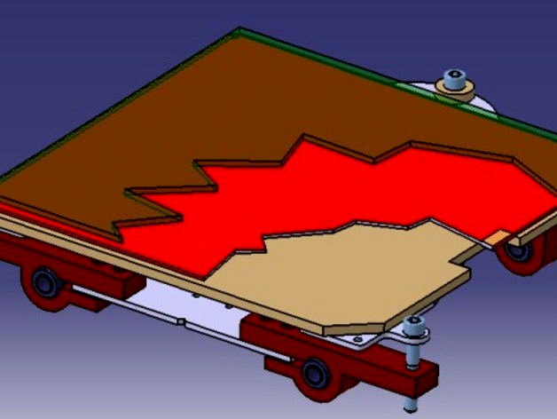
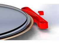
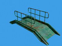
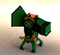
Here are some pictures of how this could be achieved:
SEE FIRST PICTURE
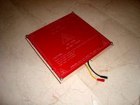
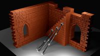
In the illustration above, we have a layered view of first, green glass, then in red, the PCB heated bed, then in brown, the 5mm cork sheet and finally in gray, the piece of laser cut 3mm aluminum.
This entire “sandwich†would be supported by the three screws shown and fixed to the ABS parts drawn in dark red. Just to ensure that this “sandwich†stays solidly assembled the M3 screws are placed in the front part (not shown) to secure the aluminum plate and PCB Heated Bed. The glass platform will be fixed with spot clamps.
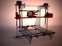
Finally the linear bearings are mounted on ABS supports and positioned with the aid of another aluminum plate which defines the frame and holds the belt.
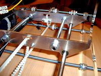
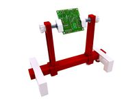
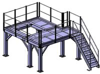
Bottom view:
SEE SECOND PICTURE
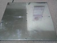
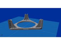
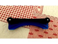
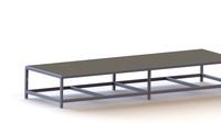
The front screws, with which the build platform is levelled, are positioned as shown below:
SEE THIRD PICTURE
The M6 screw is fixed to the ABS platform support in a way that allows the supporting assembly to rotate without having to unscrew the nut. The Aluminum platform “sandwich†base, is threaded, which causes the platform to raise or lower when the screw head is turned. Also, these are Nylon screws which do not transmit heat to the ABS supports.
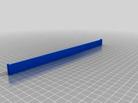
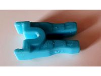
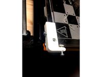
SEE FOURTH PICTURE
The rear screw will act as a ball (pivot) thanks to the elasticity of the two cork washers (5 mm thick) to allow slight pivoting rotation of the platform. Here, the Aluminum is not threaded so the height is always the same and is determined by the thickness of the cork washers. Naturally, more cork washers can be added to raise the platform and provide greater pivoting capacity.
SEE FIFTH PICTURE
Here is a dimensioned drawing of the assembly:
SEE SIXTH PICTURE
This design will suit the 148 mm standard RepRap but not the 258 mm width RepRap nor the AIR 2 design. This design is really intended for a future AIR3. Nonetheless the intention here is to present the design concept to the Open Hardware community so that we all have the opportunity to consider and modify the design for the benefit of all.
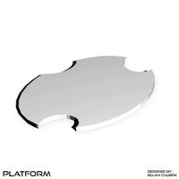
The platform plan view dimensions are shown below:
SEE SEVENTH PICTURE
As can be seen the platform is not exactly symmetrical and is centered at about 245 mm. To obtain a print area of 200 mm would require guides with a displacement length of about 445 mm and it should also should be noted that the hot-end performance must not be at the center of the 445 mm but offset at 26 mm.
We could round this off to a free travel length 450 mm with the hot-end at about 210 mm on one side and 240 on the other side.
Another important dimension to consider is the 45 mm deviation from the center of the guides to the printing surface. This distance depends largely on the thickness of the glass, aluminium and cork as well as the vertex of the upper support which has to sit above the belt. Perhaps the 45 mm clearance will be of better use to people who still use resistors to heat the bed. In any case, what is certain is that the shorter this distance is, the better as this will allow more travel of the platform in the Z-axis.
You can see the original of this article written in Spanish at:
http://reprappower.blogspot.com.es/
Or you can follow my work on twitter @RepRapPower
Solertron Thank you for helping with the translation.
The vast majority of RepRap printers use a platform bed heated by a PCB. The PCB is a square (214 mm) with holes drilled at the corners to secure it with screws (usually M3). This however does not possess the necessary rigidity and flatness which is why either a piece of glass or solid piece of aluminium is usually used to deposit the heated plastic. Because we do not print on the PCB directly, the approach is to use a piece of glass or other material that is smooth and rigid and flat. But the weight of this on our four M3 screws and springs places noticeable strain on the assembly with sometimes disappointing results.
The difficulty of accurately levelling the platform through the four M3 nuts can drive one to total madness. Clearly, one of the four nuts is redundant. That is, it is there really just to accommodate the other three. The solution then, is to place the PCB heated bed on a piece of Aluminium which is in turn supported at only three points. Three points is all that is necessary to define the plane of the platform. Now if one of these points is a ball pivot, we only have to vary the other two support points (two screws) to level our platform perfectly.
In my opinion the heated bed PCB is a component which solves in a simple, clean and efficient manner the problem of heating the printing surface. While this approach is not something that works brilliantly, the truth is that compared to the other options (wired resistors below the plate for example) I prefer the PCB heated bed.
Here are some pictures of how this could be achieved:
SEE FIRST PICTURE
In the illustration above, we have a layered view of first, green glass, then in red, the PCB heated bed, then in brown, the 5mm cork sheet and finally in gray, the piece of laser cut 3mm aluminum.
This entire “sandwich†would be supported by the three screws shown and fixed to the ABS parts drawn in dark red. Just to ensure that this “sandwich†stays solidly assembled the M3 screws are placed in the front part (not shown) to secure the aluminum plate and PCB Heated Bed. The glass platform will be fixed with spot clamps.
Finally the linear bearings are mounted on ABS supports and positioned with the aid of another aluminum plate which defines the frame and holds the belt.
Bottom view:
SEE SECOND PICTURE
The front screws, with which the build platform is levelled, are positioned as shown below:
SEE THIRD PICTURE
The M6 screw is fixed to the ABS platform support in a way that allows the supporting assembly to rotate without having to unscrew the nut. The Aluminum platform “sandwich†base, is threaded, which causes the platform to raise or lower when the screw head is turned. Also, these are Nylon screws which do not transmit heat to the ABS supports.
SEE FOURTH PICTURE
The rear screw will act as a ball (pivot) thanks to the elasticity of the two cork washers (5 mm thick) to allow slight pivoting rotation of the platform. Here, the Aluminum is not threaded so the height is always the same and is determined by the thickness of the cork washers. Naturally, more cork washers can be added to raise the platform and provide greater pivoting capacity.
SEE FIFTH PICTURE
Here is a dimensioned drawing of the assembly:
SEE SIXTH PICTURE
This design will suit the 148 mm standard RepRap but not the 258 mm width RepRap nor the AIR 2 design. This design is really intended for a future AIR3. Nonetheless the intention here is to present the design concept to the Open Hardware community so that we all have the opportunity to consider and modify the design for the benefit of all.
The platform plan view dimensions are shown below:
SEE SEVENTH PICTURE
As can be seen the platform is not exactly symmetrical and is centered at about 245 mm. To obtain a print area of 200 mm would require guides with a displacement length of about 445 mm and it should also should be noted that the hot-end performance must not be at the center of the 445 mm but offset at 26 mm.
We could round this off to a free travel length 450 mm with the hot-end at about 210 mm on one side and 240 on the other side.
Another important dimension to consider is the 45 mm deviation from the center of the guides to the printing surface. This distance depends largely on the thickness of the glass, aluminium and cork as well as the vertex of the upper support which has to sit above the belt. Perhaps the 45 mm clearance will be of better use to people who still use resistors to heat the bed. In any case, what is certain is that the shorter this distance is, the better as this will allow more travel of the platform in the Z-axis.
You can see the original of this article written in Spanish at:
http://reprappower.blogspot.com.es/
Or you can follow my work on twitter @RepRapPower
Solertron Thank you for helping with the translation.
Similar models
thingiverse
free
Y-axis Reprap redesign with integrated PCB Heatedbed. by Mecano
..., some can see the changes that have made my prusa, now called prusa air. you can see more in: http://reprap.org/wiki/prusa_air
thingiverse
free

Reprap Glass mount by jbase
...ween wood and pcb. so it goes like (from bottom):
4 mm thick wooden plate
m3 nut (standard height)
reprap hot bed pcb
4mm glass
thingiverse
free
Heated bed pillars by MiGoYang
... platform: 220mm220m3mm)
screw-m320mm1pc
nut-m3*1pc
v4:(aluminum platform: 220mm220m3mm)
pillars-5mm1pc
screw-m325mm1pc
nut-m31pc
thingiverse
free
RigidBot Heated Bed Insulation Holder by tchotchke
... may want to scale the height to make it thicker or thinner. it should be printed in abs, pc, or other high temperature plastic.
thingiverse
free
Anycubic Kossel Plus - Bed support + insulation + glass with clamp by MakeTo3D
...ightly smaller than the bed, the v2 model has less margin so it is better for glass flush with the bed.
print the parts in abs !!
thingiverse
free
Stand for soldering parts on PCB. by mkfloria
... x 35 mm - 2 pieces
nut m4 - 2 pieces
bed m4 wide - 4 pieces
spring 7,2 x 5,2 x 14 mm
self - gluing silicon rubber pad - 4 pieces
thingiverse
free
The worlds greatest heated bed mount/corner brace assembly for Kossel by adamghamel
...hen pcb 220mm heated bed and then a 200mm glass bed. also will have corner braces for 2020 frames built in. to be continued....
thingiverse
free
Bed retainer clip for Vertex K8400 /w heat by Captain_sq
...late. make sure the supply leads are filed flush with the pcb and cover it with a piece of polyamide tape to avoid short-circuit.
thingiverse
free
ANYCUBIC Delta Kossel PLUS HotBed Leveling Support by enry68
...3-05 - added new base support (v3) with external screws. easier to mount because the screws are external and can be handled easy.
thingiverse
free
Glass clamp for heated beds by jammi
... 230x200mm model):
8x 15mm or longer m3 screws
screw guide for 200x200mm glass:
8x 15mm or longer m3 screws (16..18mm is optimal)
Mecano
3d_export
$15
Mecano Chair
...>clean topology<br>units: millimeters<br>product formats:<br>3ds max 2011+ v-ray materials,<br>obj.fbx
3dbaza
$4
Chair Mecano (259075)
...chair mecano (259075)
3dbaza
chair mecano 3d model
thingiverse
free
Adaptador Hitec HS-985MG a mecano by JuanTrillo
...adaptador hitec hs-985mg a mecano by juantrillo
thingiverse
adaptador hitec hs-985mg a mecano
thingiverse
free
Mecano parts by ociotec
....
i've printed all of them with 0.6mm nozzle, 0.2mm layer height, 100% infill (no need, but i used translucent pla filament).
thingiverse
free
Mounting holes for Arduino Mega 2560 by Mecano
...can help.
i think with the eagle software can easily be seen but i'm more mechanical than electronic so i put it in dxf file.
thingiverse
free
Air 2 by Mecano
...ve been made with cinema 4d + vray by pikelo.
spanish version at:
http://reprap.org/wiki/prusa_aire#prusa_air_2.2c_redise.c3.b1o
thingiverse
free

PowerCode by Mecano
...carriage based on girobot desing, lcd suport based on bq’s prusa hephestos
license: creative commons, attribution, share alike.
thingiverse
free
Suport for Prusajr's heated bed. by Mecano
...fore it was 210 mm and 209 mm now. the dxf file has been replaced.
i have also uploaded photos of the piece steel laser-cut 3 mm.
thingiverse
free
RepRap Air by Mecano
...infographics was made by pikelo with cinema 4d + vray.
there is a wiki page writen in spanish: http://reprap.org/wiki/prusa_aire
thingiverse
free
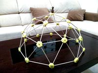
Easy assembled Geodesic Dome by Mecano
...ng:3215
but more specifically in the great labor of divulgation of obijuan (in spanish)https://github.com/tecnolab/domocraft/wiki
Platform
archibase_planet
free
Platform
...rm
archibase planet
platform
platform stefano galli savio cerrato n040413 - 3d model (*.gsm+*.3ds) for exterior 3d visualization.
turbosquid
$4
Platform
...d
royalty free 3d model platform for download as max and fbx on turbosquid: 3d models for games, architecture, videos. (1363559)
3d_export
$5
WORKING PLATFORM
...working platform
3dexport
working platform 4000x3000x1500mm
turbosquid
$20
Platform
... available on turbo squid, the world's leading provider of digital 3d models for visualization, films, television, and games.
turbosquid
$9
Platform
... available on turbo squid, the world's leading provider of digital 3d models for visualization, films, television, and games.
turbosquid
$1
Platform
... available on turbo squid, the world's leading provider of digital 3d models for visualization, films, television, and games.
turbosquid
$1

Platform
... available on turbo squid, the world's leading provider of digital 3d models for visualization, films, television, and games.
turbosquid
$1

Platform
... available on turbo squid, the world's leading provider of digital 3d models for visualization, films, television, and games.
3d_ocean
$19
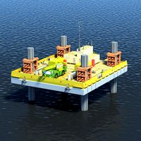
Drilling Platform
...rm for coastal areas. designed to perform drilling operations. include standart materials scene and v-ray scene with environment.
3d_export
$15
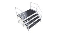
steel grill platform
...steel grill platform
3dexport
steel grill platform
Levelled
design_connected
$11

Levels
...levels
designconnected
one nordic levels computer generated 3d model. designed by form us with love.
design_connected
$7
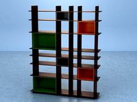
Level
...level
designconnected
zanotta level shelves and storage computer generated 3d model. designed by arik levy.
turbosquid
$29
level
...ty free 3d model level for download as 3ds, obj, c4d, and fbx on turbosquid: 3d models for games, architecture, videos. (1272856)
turbosquid
$1
level
... available on turbo squid, the world's leading provider of digital 3d models for visualization, films, television, and games.
3d_export
$5

Mario level
...mario level
3dexport
mario level low quality for fun videos
3ddd
$1
LEVELS OF DISCOVERY
...етская мебель "levels of discovery". rab10003 princess mini rocker
кресло-качалка (мини) "принцесса навсегда"
3d_export
$19
level design
...level design
3dexport
you can use this design (level design) in your own game.
turbosquid
$60
Desert level
...squid
royalty free 3d model desert level for download as fbx on turbosquid: 3d models for games, architecture, videos. (1208131)
turbosquid
$15
Transit Level
...quid
royalty free 3d model transit level for download as max on turbosquid: 3d models for games, architecture, videos. (1158112)
turbosquid
$14

Districts Level
...id
royalty free 3d model districts level for download as max on turbosquid: 3d models for games, architecture, videos. (1408410)
Easily
3d_export
$5

red flower modeling by blender
...the texture and material of the object can be easily customized in shader view blender and it is easily...
3d_export
$5

curtain modeling by blender
...object is created in blender. this curtain can be easily customized using textures and materials.<br>in blender shader, you can...
3d_export
$7
studio fabric sofa
...studio fabric sofa 3dexport you can easily change the...
3d_export
$5

Cup
...cup 3dexport blue mug, it can also be easily repainted in any...
3d_export
$5
domilli sketchup house plan
...domilli sketchup house plan 3dexport easily editable house plan for students as well as...
3d_export
$40
wood cutting and shredding machine
...wood cutting and shredding machine 3dexport it can easily shred woods up to 20 cm...
3d_export
$29

Pilot Helmet
...ready to use pilot helmet, which can be imported easily and used in...
3d_export
$15

crown splash
...file in the animated .alembic format that you can easily open in any 3d application, cinema 4d, houdini, 3dmax,...
3d_export
$16
womennp2maxfbxobjmb
...womennp2maxfbxobjmb 3dexport polygonal model of a girl.<br>you can easily snap a skeleton for...
3d_export
$7
sofa furniture l
...l 3dexport all components are separate and can be easily changed in volume. materials in the folder are...
Bolts
3d_export
$2
bolt
...
bolt - a fastener in the form of a rod with an external thread, usually with a hex head wrench, forming a connection with a nut.
3d_export
$5
bolted ring
...bolted ring
3dexport
bolted ring
3d_export
$5
royal bolt
...royal bolt
3dexport
royal bolt
turbosquid
$10
Bolt
...lty free 3d model bolt for download as max, c4d, obj, and fbx on turbosquid: 3d models for games, architecture, videos. (1681373)
turbosquid
$10

Bolt
...lty free 3d model bolt for download as max, c4d, obj, and fbx on turbosquid: 3d models for games, architecture, videos. (1680879)
turbosquid
$10

Bolt
...lty free 3d model bolt for download as max, c4d, obj, and fbx on turbosquid: 3d models for games, architecture, videos. (1680869)
turbosquid
$10

Bolt
...lty free 3d model bolt for download as max, c4d, obj, and fbx on turbosquid: 3d models for games, architecture, videos. (1680866)
turbosquid
$10
Bolt
...lty free 3d model bolt for download as max, c4d, obj, and fbx on turbosquid: 3d models for games, architecture, videos. (1680860)
turbosquid
$10

Bolt
...lty free 3d model bolt for download as max, c4d, fbx, and obj on turbosquid: 3d models for games, architecture, videos. (1680480)
turbosquid
$13
bolt
... available on turbo squid, the world's leading provider of digital 3d models for visualization, films, television, and games.
Only
3d_export
$7

sneakers only
...sneakers only
3dexport
3ddd
$1

Coffee table only
...coffee table only
3ddd
журнальный
coffee table only, журнальный стол
turbosquid
$18
Only you Zen
...squid
royalty free 3d model only you zen for download as max on turbosquid: 3d models for games, architecture, videos. (1372551)
turbosquid
$16
House (Exterior only)
... available on turbo squid, the world's leading provider of digital 3d models for visualization, films, television, and games.
turbosquid
$7

Orc (mesh only)
... available on turbo squid, the world's leading provider of digital 3d models for visualization, films, television, and games.
turbosquid
$6

Fox (mesh only)
... available on turbo squid, the world's leading provider of digital 3d models for visualization, films, television, and games.
turbosquid
$6

Nebula (mesh only)
... available on turbo squid, the world's leading provider of digital 3d models for visualization, films, television, and games.
turbosquid
$5

Hedgehog (mesh only)
... available on turbo squid, the world's leading provider of digital 3d models for visualization, films, television, and games.
turbosquid
$5

Witch (mesh only)
... available on turbo squid, the world's leading provider of digital 3d models for visualization, films, television, and games.
turbosquid
$5

Woody (mesh only)
... available on turbo squid, the world's leading provider of digital 3d models for visualization, films, television, and games.
Two
turbosquid
$4

Two Axes Two States
...free 3d model two axes two states for download as obj and fbx on turbosquid: 3d models for games, architecture, videos. (1468396)
3d_export
$5
s of two one and two
...blender file. one burner cooker: vertices: 16,221 faces: 14,780 triangle: 31,490 two burner stove: vertices: 25,200 faces: 23,625
turbosquid
$20
two
...osquid
royalty free 3d model two for download as 3ds and stl on turbosquid: 3d models for games, architecture, videos. (1435051)
3ddd
$1
avec two
...avec two
3ddd
jmm , avec two
jmm avec two
3ddd
$1
cea two
... вентилятор , потолочный
cea two
все размеры
vray+corona
3d_export
$5
Two speaker
...two speaker
3dexport
this is a 3d model of two speakers from sven
3d_export
free
Two wall
...two wall
3dexport
two wall<br>.blend
design_connected
$29

All-Two
...all-two
designconnected
bonaldo all-two computer generated 3d model. designed by bicego, sergio.
design_connected
$9

Two Timer
...two timer
designconnected
established & sons two timer computer generated 3d model. designed by industrial facility.
turbosquid
$21
DAVENTRY Two Over Two Chest of Drawers
... chest of drawers for download as max, max, max, fbx, and obj on turbosquid: 3d models for games, architecture, videos. (1684477)