Thingiverse
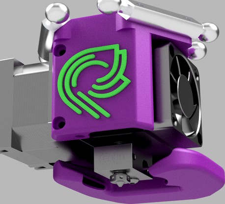
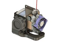
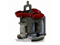
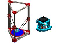
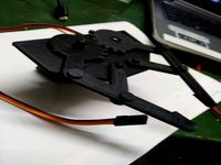
E3D Hemera Effector Mount for Delta Printers
by Thingiverse
Last crawled date: 4 years, 2 months ago
An effector and fan shroud mount for the E3D Hemera for delta printers.
This direct drive effector works quite well with well designed delta printers like the Ultibots D300VS or the various SeeMeCNC printers that use the SeeMeCNC machined aluminum barbells.
Update:
Added a new fan duct that has a much more optimized air flow. Print the Hemera Claws Fan Duct.stl file, not the other fan manifold file. This Claws manifold is loosely based on Hangtight's Hemera fan duct, but is made from the ground up in Fusion 360.
Older Updates:
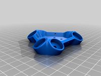
Added a universal mount. This has 3 holes placed around the perimeter for heatserts. Use these to mount an adapter for other deltas. See drawing for relevant dimensions.
Added 35mm face mount ball stud and Traxxis 40mm mount. I have not tested these.
Printing
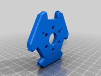
Print the effector with the top facing the bed. Supports are built into the models. The fan shroud should be printed with the blower mouth facing up. Trim off the bands tying the barbell studs together and remove the two pieces that support the shelf at the rear.
Some good print settings for PrusaSlicer:
0.2 Layer Height
4 Walls
5 Top and Bottom layers
40% infill - Triangle
Detect Thin Walls : Off
Bridge Angle: 0 (Auto - verify the bridges are in the direction where they are shortest)
I like to print with 0.6mm extrusion width with a 0.4mm nozzle for more strength. 0.4 or 0.48mm extrusion width should be ok too.
Print the Effector and especially the Fan Manifold with a higher temperature filament. PLA and PETG can droop with the heat. I recommend SnoLabs PC+ which is easily printable without enclosure. Esun ABS+ would be another good choice.
Parts
To assemble the effector mount you will need the following parts and hardware:
1 E3D Hemera Direct Drive Extruder
1 5015 blower - Delta BFB0524HH for 24V, Sunon MF50151V1-B00U-A99 for 12V work well. Mouser.com carries both.
3 SeeMeCNC Barbells](https://www.seemecnc.com/collections/parts-accessories) Use the metal barbells. The plastic ones are too flexy.
10 M3x12m Screws (2 for Front to Hemera, 6 for barbells, 2 for fan bracket mount
2 M3x20mm Screws (Fan to fan shroud)
2 M3X6mm Screws (Rear to Hemera, Fan shroud to Hemera x2,)
9 M3 x 4mm x 5mm Heatserts - the cheap ones on Amazon or AliExpress, not the nice McMaster heatserts. M3 x 5mm x 5mm are too big
Optional tie screws to strengthen the mount.
1 M3x50mm Screw
1 M3x12mm Screw
2 M3 Heatserts
1 60mm (or similar length) M3 Screw for the whip mast. Can also substitute a 3mm rod.
~1M Braided wrap around sleeving. This is much easier than spiral wraps.
All M3 hardware can be button head or socket head.
Assembly
You will need to make a trivial modification to the Hemera extruder/stepper assembly to rotate the face so the rear wires exit in a way that doesn't interfere with the delta arms. To do this, merely unscrew the 4 phillips screws on the back of the Hemera Stepper. Using a spatula, pry the face off (it should come easy). Slide the face off and rotate it 90 degrees clockwise and reassemble.
Insert M3 heatserts into the 6 barbell mounting studs. I found it easiest to use a 40mm or so long screw inserted through the hole from the top. Screw a heatsert onto the screw, heat with a lighter and pull the heatsert into place.
Heatserts also go in the mast mount on the top, the fan mount hole on the effector and the fan mount hole on the fan shroud. Insert a heatsert in the hole at the bottom of the front face, flush against the bottom. It is used both for the stiffening screw and to attach the optional front facade.
Optional but recommended: I have provided holes and relief for heatserts to stiffen the front and rear arms which mount to the Hemera. Since the layer lines are horizontal, these arms could be weaker than necessary. Screws thru their length stiffens them up. On the front 50mm m3 screw screws into a heatsert at the bottom of the arm. On the rear, 2 12mm screws come in from the bottom to heatserts inserted on the top.
Attach the stepper motor connector to the stepper, the thermistor with it's cable and the heater cartridge. Route those wires up behind the front brace and through the effector top. The Hemera fan wires also route up similarly. The part cooling fan wires run along the bottom of the Hemera and up this chase.
Carefully fit the Hemera into the Effector, taking up slack in the wires. Attach the Hemera with two M3x12 screws on the front and a single M3x8 screw on the back.
Attach the barbells. They should seat against the angled face. If not, you may need to file the spigots to allow the barbells to seat properly.
Insert a single M3 square nut into the bottom rear slot of the Hemera stepper. Attach the blower with an M3x8 screw on the side and an M3x12 screw on the bottom.
A long M3 screw or rod can be affixed to the hole in the top of the effector to act as a whip mast. Wrap the wires with cable wrap and zip tie them to the mast with a couple zip ties.
with.
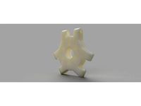
Optional: Print out the Hemera Logo pieces and CA glue them into the insets. Use the regular logo for the main effector, or the thick ones for the facade. I printed the main one in color changing PLA.
Print Settings with the Effector
You will want to tune your print settings. I have found the following has minimal ringing yet reasonably fast print speed:
M201 X850 Y850 Z850 E1000 ; Accelerations (mm/s^2)
M203 X20000 Y20000 Z20000 E3600 ; Maximum speeds (mm/min) -
M566 X370 Y370 Z370 E300 ; Maximum instant speed changes mm/minute
M566 values may be a little low. need more testing.
These values were tuned by using Kisslicer's wizard.
TBD: M593 Dynamic Acceleration Adjustment. Preliminary results were no improvement.
This direct drive effector works quite well with well designed delta printers like the Ultibots D300VS or the various SeeMeCNC printers that use the SeeMeCNC machined aluminum barbells.
Update:
Added a new fan duct that has a much more optimized air flow. Print the Hemera Claws Fan Duct.stl file, not the other fan manifold file. This Claws manifold is loosely based on Hangtight's Hemera fan duct, but is made from the ground up in Fusion 360.
Older Updates:
Added a universal mount. This has 3 holes placed around the perimeter for heatserts. Use these to mount an adapter for other deltas. See drawing for relevant dimensions.
Added 35mm face mount ball stud and Traxxis 40mm mount. I have not tested these.
Printing
Print the effector with the top facing the bed. Supports are built into the models. The fan shroud should be printed with the blower mouth facing up. Trim off the bands tying the barbell studs together and remove the two pieces that support the shelf at the rear.
Some good print settings for PrusaSlicer:
0.2 Layer Height
4 Walls
5 Top and Bottom layers
40% infill - Triangle
Detect Thin Walls : Off
Bridge Angle: 0 (Auto - verify the bridges are in the direction where they are shortest)
I like to print with 0.6mm extrusion width with a 0.4mm nozzle for more strength. 0.4 or 0.48mm extrusion width should be ok too.
Print the Effector and especially the Fan Manifold with a higher temperature filament. PLA and PETG can droop with the heat. I recommend SnoLabs PC+ which is easily printable without enclosure. Esun ABS+ would be another good choice.
Parts
To assemble the effector mount you will need the following parts and hardware:
1 E3D Hemera Direct Drive Extruder
1 5015 blower - Delta BFB0524HH for 24V, Sunon MF50151V1-B00U-A99 for 12V work well. Mouser.com carries both.
3 SeeMeCNC Barbells](https://www.seemecnc.com/collections/parts-accessories) Use the metal barbells. The plastic ones are too flexy.
10 M3x12m Screws (2 for Front to Hemera, 6 for barbells, 2 for fan bracket mount
2 M3x20mm Screws (Fan to fan shroud)
2 M3X6mm Screws (Rear to Hemera, Fan shroud to Hemera x2,)
9 M3 x 4mm x 5mm Heatserts - the cheap ones on Amazon or AliExpress, not the nice McMaster heatserts. M3 x 5mm x 5mm are too big
Optional tie screws to strengthen the mount.
1 M3x50mm Screw
1 M3x12mm Screw
2 M3 Heatserts
1 60mm (or similar length) M3 Screw for the whip mast. Can also substitute a 3mm rod.
~1M Braided wrap around sleeving. This is much easier than spiral wraps.
All M3 hardware can be button head or socket head.
Assembly
You will need to make a trivial modification to the Hemera extruder/stepper assembly to rotate the face so the rear wires exit in a way that doesn't interfere with the delta arms. To do this, merely unscrew the 4 phillips screws on the back of the Hemera Stepper. Using a spatula, pry the face off (it should come easy). Slide the face off and rotate it 90 degrees clockwise and reassemble.
Insert M3 heatserts into the 6 barbell mounting studs. I found it easiest to use a 40mm or so long screw inserted through the hole from the top. Screw a heatsert onto the screw, heat with a lighter and pull the heatsert into place.
Heatserts also go in the mast mount on the top, the fan mount hole on the effector and the fan mount hole on the fan shroud. Insert a heatsert in the hole at the bottom of the front face, flush against the bottom. It is used both for the stiffening screw and to attach the optional front facade.
Optional but recommended: I have provided holes and relief for heatserts to stiffen the front and rear arms which mount to the Hemera. Since the layer lines are horizontal, these arms could be weaker than necessary. Screws thru their length stiffens them up. On the front 50mm m3 screw screws into a heatsert at the bottom of the arm. On the rear, 2 12mm screws come in from the bottom to heatserts inserted on the top.
Attach the stepper motor connector to the stepper, the thermistor with it's cable and the heater cartridge. Route those wires up behind the front brace and through the effector top. The Hemera fan wires also route up similarly. The part cooling fan wires run along the bottom of the Hemera and up this chase.
Carefully fit the Hemera into the Effector, taking up slack in the wires. Attach the Hemera with two M3x12 screws on the front and a single M3x8 screw on the back.
Attach the barbells. They should seat against the angled face. If not, you may need to file the spigots to allow the barbells to seat properly.
Insert a single M3 square nut into the bottom rear slot of the Hemera stepper. Attach the blower with an M3x8 screw on the side and an M3x12 screw on the bottom.
A long M3 screw or rod can be affixed to the hole in the top of the effector to act as a whip mast. Wrap the wires with cable wrap and zip tie them to the mast with a couple zip ties.
with.
Optional: Print out the Hemera Logo pieces and CA glue them into the insets. Use the regular logo for the main effector, or the thick ones for the facade. I printed the main one in color changing PLA.
Print Settings with the Effector
You will want to tune your print settings. I have found the following has minimal ringing yet reasonably fast print speed:
M201 X850 Y850 Z850 E1000 ; Accelerations (mm/s^2)
M203 X20000 Y20000 Z20000 E3600 ; Maximum speeds (mm/min) -
M566 X370 Y370 Z370 E300 ; Maximum instant speed changes mm/minute
M566 values may be a little low. need more testing.
These values were tuned by using Kisslicer's wizard.
TBD: M593 Dynamic Acceleration Adjustment. Preliminary results were no improvement.
Similar models
thingiverse
free

MGN12 SeeMeCNC Barbell Carriage for Delta Printer (D300VS and others)
...ails when mounting them.
also check out my hemera mount that also uses seemecnc barbellshttps://www.thingiverse.com/thing:4027625
thingiverse
free
E3D Titan Aero Part Cooling 40x20mm Blower Fan Mount and Shroud by NorcoT
...otend to allow for silicone heater block cover. removed 1 of the fan screw holes. added a tab/hole for cable tie point for wires.
thingiverse
free

Hemera + Volcano Ender 3 Cooling Duct by Mapleguy
...ender 3. mounts to the 'front' end of the hemera and uses threaded inserts and screws to mount a 40mm fan. all m3 screws.
thingiverse
free

Orbiter adapter for Duet Smart effector Delta printers by lorinczroby
... nuts + 2x m3 insert nuts in the adapter for mounting the orbiter on top.
thanks frank g. for helping and supporting this design.
thingiverse
free

E3d upgrade for Wombot Exllis by Paul3163
...y screws from jaycar.
design files are included
40mm fan adaptor was from the link belowhttps://www.thingiverse.com/thing:2572641
thingiverse
free

Dual fan mount for standard delta kossel effector e3dv6 by kazolar
...ngiverse
fan shrouds which are attached using a regular screws which you normally clamp the e3dv6 to a standard kossel effector.
thingiverse
free

Delta Effector with integraded fan shroud by Aslansmonkey
...ified the 40mm version to have an integrated fan shroud flush with the bottom of the effector. this is working well on my flsun.
thingiverse
free

Delta Kossel Effector 3x 40mm Fan BLTouch Sensor by CaptainRoot
...ew 12mm
2 m3 screew 16mm
or even better when widen the holes with a drill
2 thermoplast screws 3x12
2 thermoplast screws 3.5 x 16
thingiverse
free

Upgrade Effector with round fan duct for Kossel / Delta (D810) by Tysonpower
...15 blower type fan (optional)
i designed the effector for my zonestar d810, but it should fit any kossel (~20x30cm build volume).
thingiverse
free

ReDuplicator i3 MK3x - E3D Hemera Mount with Bltouch and Filament Sensor
...nut m4 soft washer the installation process is very similar to the original mk10 hotend and the titan aero....
Hemera
3ddd
$1

Hemera
...d
круглое , напольные
зеркало hemera;
designer:grace feyock
dimensions:46 w x 46 h x 1 d
3ddd
$1

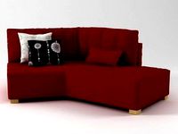
Cофа (MOS)
...cофа (mos) 3ddd угловой hemera l-shape sofa. смоделена по реальным...
3d_sky
free

PROFI Hemera
...profi hemera
3dsky
hemera mirror;
designer: grace feyock
dimensions: 46 w x 46 h x 1 d
thingiverse
free

E3D Hemera Model
...e3d hemera model
thingiverse
official mounting cad for designing your own custom mounts for the e3d hemera.
thingiverse
free

Hemera Troodon mount by vonsy
...hemera troodon mount by vonsy
thingiverse
hemera support for troodon
thingiverse
free

BLTouch Mount for Hemera
...bltouch mount for hemera
thingiverse
attach to hemera heat sink body with 3m vhb tape flush to the top edge.
thingiverse
free

X5S MGN12 Hemera by Festivejelly
... mounting solution for the e3d hemera on a mgn12 rail.
assemble and screw the hemera into the mount before putting onto the rail.
thingiverse
free

Hemera Mount for 2020 (2040)
...hemera mount for 2020 (2040)
thingiverse
2020 mount for the e3d hemera (hermes)
thingiverse
free

MGN12 Toprail mount for Hemera
...mgn12 toprail mount for hemera
thingiverse
hemera mount for mgn12 rails on top like the am8
thingiverse
free

E3D Hemera Blower Duct
...e3d hemera blower duct
thingiverse
blower duct & mount. fits e3d hemera extruder
Effector
3d_ocean
$5

Radial Sound Effector
...e spheres will expand with your song. fully customisable, change the color, the size of the spheres or even put in different s...
3d_ocean
$12

3D Customizable Puzzle Set (16x10)
...mograph compatible (you can effect the pieces with mograph effector) - included also a non-mograph version with...
thingiverse
free
Effector by olo2000pm
...effector by olo2000pm
thingiverse
effector
thingiverse
free
CERAMBOT-Effector
...cerambot-effector
thingiverse
cerambot-effector
thingiverse
free

modulize effector by candyasdf
...ulize effector by candyasdf
thingiverse
mount things on effector with m3 screws
effector radius : 25.4mm
rod arm distance : 40mm
thingiverse
free
Delta Effector by zavier
...delta effector by zavier
thingiverse
delta effector with radial fan 50 and bltouch
thingiverse
free
D810 Effector by WhiteTiger13
...d810 effector by whitetiger13
thingiverse
this is d810 effector for d810 without autocalibration, and also cap for it.
thingiverse
free
Effector for Delta Printer
...effector for delta printer
thingiverse
effector for delta printer (3 color)
using diamond hotend
thingiverse
free
Delta effector magnetic by fpassos
...delta effector magnetic by fpassos
thingiverse
effector for e3dv6 hotend. i needed put the spheres (10mm) on the effector.
thingiverse
free
End Effector Gripper
...end effector gripper
thingiverse
end effector gripper
for a robotic arm
uses mg995 servo motor
Delta
design_connected
$16

Delta
...delta
designconnected
arflex international spa delta computer generated 3d model. designed by koivisto, eero.
design_connected
$16

Delta
...delta
designconnected
lj lamps delta computer generated 3d model. designed by janowski-lenhart, sasha.
design_connected
$13

Delta
...delta
designconnected
emu group delta armchairs computer generated 3d model. designed by marin chiaramonte .
3ddd
$1
Delta Light
...delta light
3ddd
delta light , you-turn reo 3033
точечний светильник delta light
3ddd
$1
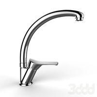
Blanco / delta
...blanco / delta
3ddd
blanco , мойка
мойка blanco delta со смесителем
3ddd
$1
Delta Light Spot
...delta light spot
3ddd
delta light
светильник фирмы delta light
3ddd
free
Bianchi Delta LVMDLT200100
...i delta lvmdlt200100
3ddd
bianchi delta , смеситель
смеситель bianchi delta lvmdlt200100
design_connected
free
Delta 190
...delta 190
designconnected
free 3d model of delta 190 by zanotta designed by progetti, emaf.
design_connected
$27

Delta 211
...delta 211
designconnected
zanotta delta 211 computer generated 3d model. designed by progetti, emaf.
design_connected
$27

Delta 234
...delta 234
designconnected
zanotta delta 234 computer generated 3d model. designed by progetti, emaf.
E3D
turbosquid
$23

E3D - Google Home
... 3d model e3d - google home for download as max, obj, and c4d on turbosquid: 3d models for games, architecture, videos. (1192509)
cg_studio
free

e3d model
...e3d model
cgstudio
- e 3d model, royalty free license available, instant download after purchase.
turbosquid
$2
Syringe C4D (E3D Ready)
...lty free 3d model syringe c4d (e3d ready) for download as c4d on turbosquid: 3d models for games, architecture, videos. (1336720)
turbosquid
$12
Microphone USB E3D and C4D
...ree 3d model microphone usb e3d & c4d for download as c4d on turbosquid: 3d models for games, architecture, videos. (1568216)
turbosquid
$29

E3D - OnePlus 6 Black
...model e3d - oneplus 6 black for download as max, obj, and c4d on turbosquid: 3d models for games, architecture, videos. (1358534)
turbosquid
$29

E3D - Motorola One 2018
...del e3d - motorola one 2018 for download as max, obj, and c4d on turbosquid: 3d models for games, architecture, videos. (1358533)
turbosquid
$29
E3D - Disney MagicBands 2
...l e3d - disney magicbands 2 for download as max, obj, and c4d on turbosquid: 3d models for games, architecture, videos. (1355515)
turbosquid
$29

E3D - Samsung Z4 Smartphone
...e3d - samsung z4 smartphone for download as max, obj, and c4d on turbosquid: 3d models for games, architecture, videos. (1182179)
turbosquid
$23

E3D - Razer Phone model
...del e3d - razer phone model for download as max, obj, and c4d on turbosquid: 3d models for games, architecture, videos. (1231207)
turbosquid
$23

E3D - Alcatel Idol 5
... model e3d - alcatel idol 5 for download as max, obj, and c4d on turbosquid: 3d models for games, architecture, videos. (1212799)
Printers
archibase_planet
free
Printer
...inter
archibase planet
printer laser printer pc equipment
printer n120614 - 3d model (*.gsm+*.3ds) for interior 3d visualization.
archibase_planet
free
Printer
...rchibase planet
laser printer office equipment computer equipment
printer - 3d model (*.gsm+*.3ds) for interior 3d visualization.
turbosquid
$100
Printer
...er
turbosquid
royalty free 3d model printer for download as on turbosquid: 3d models for games, architecture, videos. (1487819)
turbosquid
$3
Printer
...turbosquid
royalty free 3d model printer for download as max on turbosquid: 3d models for games, architecture, videos. (1670230)
turbosquid
$1
printer
...turbosquid
royalty free 3d model printer for download as max on turbosquid: 3d models for games, architecture, videos. (1595546)
turbosquid
$1
printer
...turbosquid
royalty free 3d model printer for download as max on turbosquid: 3d models for games, architecture, videos. (1595105)
turbosquid
$10
Printer
...id
royalty free 3d model printer for download as max and 3dm on turbosquid: 3d models for games, architecture, videos. (1607146)
turbosquid
$7
Printer
...royalty free 3d model printer for download as ma, ma, and obj on turbosquid: 3d models for games, architecture, videos. (1644580)
turbosquid
$30
Printer
... available on turbo squid, the world's leading provider of digital 3d models for visualization, films, television, and games.
turbosquid
$20
Printer
... available on turbo squid, the world's leading provider of digital 3d models for visualization, films, television, and games.
Mount
3d_export
free

mounting bracket
...mounting plate is the portion of a hinge that attaches to the wood. mounting plates can be used indoors, cabinetry and furniture.
turbosquid
$2

MOUNTING
... available on turbo squid, the world's leading provider of digital 3d models for visualization, films, television, and games.
turbosquid
free

Mounts
... available on turbo squid, the world's leading provider of digital 3d models for visualization, films, television, and games.
turbosquid
free

Mount Fuji
...fuji
turbosquid
free 3d model mount fuji for download as obj on turbosquid: 3d models for games, architecture, videos. (1579977)
3d_export
$5

Headphone mount LR
...headphone mount lr
3dexport
headphone mount l+r
turbosquid
$39

Mount rainier
...quid
royalty free 3d model mount rainier for download as fbx on turbosquid: 3d models for games, architecture, videos. (1492586)
turbosquid
$5

pipe mounting
...quid
royalty free 3d model pipe mounting for download as obj on turbosquid: 3d models for games, architecture, videos. (1293744)
turbosquid
$3

Mounting Tires
...uid
royalty free 3d model mounting tires for download as fbx on turbosquid: 3d models for games, architecture, videos. (1708511)
3d_export
$5

Magnetic GoPro Mount
...pro mount
3dexport
cool magnetic mount for gopro. allows you to mount the camera on flat metal surfaces and get exclusive shots.
turbosquid
$5

Stone Mount
...ty free 3d model stone mount for download as ma, obj, and fbx on turbosquid: 3d models for games, architecture, videos. (1370306)