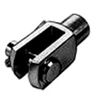
Thingiverse
Dual Power Supply Front End - alt lab supply by MCmaks
by Thingiverse
Last crawled date: 3 years ago
An inexpensive alternative to a dual output DC lab supply. Essentially a power supply front-end with voltage adjustment buttons, LCDs for voltage and current readings, banana jacks / binding posts, DC jack, and power switch. Built around two DC-DC buck converter boards; output 0-16.5VDC, 3A peak, 2A continuous (times two boards/channels). I haven't tested the power specs to the max, but I did include mounting for a cooling fan (untested). The total parts cost is about 10 USD. It needs a positive tip power supply under 23VDC not included in that total; laptop chargers are pretty much ideal (~20V, >3 A).
Single Output Version
Thanks for the CAD models:
Banana jacks by Jeroen LodderSwitch by Milan Samardzija30mm fan by Phil Maddox
BOM:
Find the tip size of your wall-wart/AC adapter before buying the DC jack. Links for 5.5mm x 2.1mm as well as 5.5mm x 2.5mm are included below. The list includes things I suspect most people already have like screws and an AC adapter. Assuming those are on-hand and the fan isn't installed, I calculated 8.44 USD for parts actually used (items 1 - 4 below). I selected parts with free shipping when possible, but some parts have minimum order quantities above what's needed.
1) DC-DC converter board, qty 2
2) Banana jacks, link is already qty 2
3) Switch
4) DC jack, select your tip size
5) Optional, fan (30mm, 24V)
6) DC DC board screws, M2.5 x 5
7) Bottom cover screws, M3 x 5
8) Optional, rubber feet
9) Wire
10) Power supply, 2.5mm positive tip and cable
Assembly Instructions (video is for single, dual is similar):
1) Print the body, bottom cover, and four buttons. Make sure the print bed is smooth because the bottom layer becomes the top of the assembled unit. (The texture of tape or glue may be transferred.) Fan guard regions and buttons may need some filing/pruning and you can cut off the single support rib on the back.
2) Optional: Paint/color the recessed text and the buttons.
3) Install the buttons; drop in, check they move freely and drop all the way down.
4) De-solder/remove the large blue terminal blocks from the DC-DC converter boards. Clean out (wick or sucker) the plated thru-holes. Adding wires to Vin/GND and Vout/GND may make wiring easier later.
5) Install the DC-DC converter boards using M2.5 X 5mm screws (4X). The screw bosses should be effectively self-tapping. Check that the buttons now "pop" when pressed and when released.
6) Install the DC power jack, switch, and banana jacks.
7) Wiring: Use a fairly high-powered iron (GND plane and beefy bananas can suck the heat away before the temp gets high enough to melt the solder).
Solder red wires: DC jack+ to switch_in, switch_out to DC-DC boards' Vin [2X], DC-DC boards' Vout to red bananas [2X]. Make sure the polarity to Vin is correct!
Solder black wires: DC jack GND to DC-DC boards' GND [by Vin, 2X], DC-DC boards' GND(by Vout) to black bananas [2X].
8) Optional: Install and solder in the fan (black to DC jack GND and red to switch_out), not yet tested. I think the screws are M3 x 16mm in the CAD model. Mind the fan blades and wiring (include internal fan guard?) Mind the fan's voltage rating ... they usually have minimum voltages around half the nominal voltage, but max voltages not much over the nominal. So most 24V fans should be okay at 20V, but 12V fans would not be.
9) Install the bottom cover with M3x5 flathead screws (6X). They should self-tap into the body.
10) Optional: Apply small adhesive rubber feet (4X).
https://youtu.be/I5ZASDWc5L0https://youtu.be/0Hl5d5YSglQ
Similar models
thingiverse
free

Power Supply Front End - Alt Lab Supply by MCmaks
...f-tap into the body.
9) optional: apply small adhesive rubber feet (4x).
https://youtu.be/syrfwwdw3rwhttps://youtu.be/0hl5d5ysglq
grabcad
free

dc 12v to 5v buck converter
... board dc 4.5-20v 12v 9v step down to 1-16v 5v reducer 3a fixed adjustable volt output transformer power supply stabilizer module
thingiverse
free

DIY Power Supply DPS5005 by RianB
...electronic stores) ac-dc converter (geekcreit 36v 180w ac-dc or similar form factor/hole spacing) on/off switch (rocker switch) fuse holder...
thingiverse
free

DIY portable DC/DC step-up power supply (with XL6009) by Batbx
...rn in my case to get precise voltage adjustment)
2 * 5a fuse
2 * 5/10a diodes
2 * 5.5 mm dc female jack
1 * xt60 female connector
thingiverse
free

Power supply with adjustable voltage by MDavid12
...socket female panel mount connector 5.5mm x 2.1mm
-voltage display dc meter 3-digital mini voltmeter wires led 0-30v panel tester
thingiverse
free

HP DPS-700GB 80mm fan shroud by SanguineDrone
....
please let me know if you have any questions or issues. printed on a lulzbot taz6 with .5mm nozzle head and .35mm layer height.
grabcad
free

NodeMcu Base ver 1.0
..., dc step-down converter circuit, dc jack input voltage: 6v-24vdc, on-board power indicator, usb power output only for nodemcu v3
thingiverse
free

D3806 DC-DC Buck Boost Converter 38v - Power Supply - Box by paul0
...able
female socket
3d printing
1x front panel
1x back panel
1x top
1x bottom
4x foot
4x button
note: you need to glue the buttons
grabcad
free

2-way Banana Plug Jack
...2-way banana plug jack
grabcad
used as speaker terminals or bench power supply dc output terminals
thingiverse
free

DFROBOT 5A MODULE ENCLOSURE by FrancescoOnorati
...led high to turn the converter module on and low to turn it off.
cautions: the input voltage must be higher than output voltage.
Mcmaks
thingiverse
free

Laptop lady by MCmaks
... pillar supports in slic3r ... be careful with the sun when removing the supports. silhouette filled with white correcting fluid.
thingiverse
free

Remix RepRap Discount case -- For 2020 Mount FLSun i3 by MCmaks
...remix reprap discount case -- for 2020 mount flsun i3 by mcmaks
thingiverse
mounting holes for 2020 plus lcd wire guides.
thingiverse
free

Weighted number blocks -- Slide version by MCmaks
...in/out. nickels (us) can be used to weight blocks proportionally. compatible with scale:https://www.thingiverse.com/thing:2517509
thingiverse
free
Triangle Properties Learning Aid -- Big version by MCmaks
...mm side lengths.
** i haven't printed this yet -- work in progress.
small version: https://www.thingiverse.com/thing:2519895
thingiverse
free

Closet organizer clips by MCmaks
...ve versions may be easier to print (no support issues), but may need to be painted to have adequate contrast inside dark closets.
thingiverse
free
Whiteboard compass by MCmaks
...arent-hanger-kitchen-bathroom-suction-cup-sucker-20mm/311566424293?sspagename=strk%3amebidx%3ait&_trksid=p2060353.m2749.l2649
thingiverse
free
Whiteboard game spinner by MCmaks
...arent-hanger-kitchen-bathroom-suction-cup-sucker-20mm/311566424293?sspagename=strk%3amebidx%3ait&_trksid=p2060353.m2749.l2649
thingiverse
free

2020 RA Spool Holder with Filtered Filament Guide by MCmaks
...ll piece of foam (10mm x 10mm x 5mm uncompressed) with a hole punched in the middle. filament guide has supports in the stl file.
thingiverse
free
Triangle Properties Learning Aid by MCmaks
...version in the works: https://www.thingiverse.com/thing:2520435
i used no supports or bed adhesion, 0.2mm layer height, i3 clone.
thingiverse
free
Stackable file paper holder organizer - pencil struts by MCmaks
...(1.375" x 1.875"); cut card stock or use small self-stick note. scrap cardboard for the platforms; i used a cereal box.
Alt
3ddd
$1
Alt Reed
... reed , alt reed
alt reed. 3 размера. pl 90, 135, 180
3ddd
$1

Alt Lucialternative
...alt lucialternative
3ddd
alt lucialternative
люстра alt lucialternative в трех цветах
3ddd
$1
Alt Lucialternative
...cialternative , потолочный светильник
потолочный светильник alt lucialternative
turbosquid
$55
Alt
... available on turbo squid, the world's leading provider of digital 3d models for visualization, films, television, and games.
3ddd
free

Alt coupole S
... подвес , alt lucialternative
подвес alt coupole
3ddd
$1
alt lucialternative joy
...alt lucialternative joy
3ddd
alt lucialternative
max 2009, v-ray
turbosquid
$3

Alt Berlin
...ty free 3d model alt berlin for download as max, obj, and fbx on turbosquid: 3d models for games, architecture, videos. (1466349)
3ddd
$1

Alt Lucialternative Cherry lamp
...ternative , cherry
ceiling lamp from alt lucialternative designed by alessandro crosera.
3ddd
free

Alt Group / La Fenice
... капитоне
прикроватная банкетка, производитель alt group (italy), в серии кровати la fenice
turbosquid
$5

Table 80x80 alt
... available on turbo squid, the world's leading provider of digital 3d models for visualization, films, television, and games.
Lab
3ddd
$1
Lab
...lab
3ddd
hkliving , lab
lab 13x13x17cm,
lab xl 36x36x32cm
3ddd
$1

Смеситель Lab
...смеситель lab
3ddd
barazza , lab
кухонный смеситель barazza;
модель lab.
3d_export
$5
Lab Tray
...lab tray
3dexport
lab tray 3d model that can be used in movies and games.<br>suitable for lab and hospital environments.
3ddd
$1
Lab Line
...lab line
3ddd
turbosquid
$149

Computer Lab
...squid
royalty free 3d model computer lab for download as lwo on turbosquid: 3d models for games, architecture, videos. (1676076)
turbosquid
$90

Crashed lab
...osquid
royalty free 3d model crashed lab for download as max on turbosquid: 3d models for games, architecture, videos. (1426371)
turbosquid
$5

Lab Table
...rbosquid
royalty free 3d model lab table for download as obj on turbosquid: 3d models for games, architecture, videos. (1703851)
turbosquid
$99

Kids Lab
...alty free 3d model kids lab for download as c4d, obj, and fbx on turbosquid: 3d models for games, architecture, videos. (1699149)
turbosquid
$19
Lab Flask
...y free 3d model lab flask for download as obj, fbx, and blend on turbosquid: 3d models for games, architecture, videos. (1245982)
turbosquid
free

Lab bench
...ree 3d model lab bench for download as jpg, obj, fbx, and stl on turbosquid: 3d models for games, architecture, videos. (1472590)
Dual
turbosquid
free

Dual Pistols
...ls
turbosquid
free 3d model dual pistols for download as fbx on turbosquid: 3d models for games, architecture, videos. (1320360)
turbosquid
$2
Dual Axe
...urbosquid
royalty free 3d model dual axe for download as fbx on turbosquid: 3d models for games, architecture, videos. (1332372)
turbosquid
$10
Dual Lesaths
... available on turbo squid, the world's leading provider of digital 3d models for visualization, films, television, and games.
3ddd
$1
плитка Dual Bianco (Испания)
...й плитки venis dual (испания). технические качества: устойчивость к стирания, отличная геометрия, отсутствие проблем при укладке.
turbosquid
$35

Dual Mesh Fonts
...ree 3d model dual mesh fonts for download as ma, obj, and fbx on turbosquid: 3d models for games, architecture, videos. (1352989)
turbosquid
$29

Dual Flask with Bungs
...del dual flask with bungs for download as obj, fbx, and blend on turbosquid: 3d models for games, architecture, videos. (1210512)
turbosquid
$19
Dual Socket Plug
...3d model dual socket plug for download as obj, fbx, and blend on turbosquid: 3d models for games, architecture, videos. (1303912)
turbosquid
$13
Dual Adjustable Pulley
... available on turbo squid, the world's leading provider of digital 3d models for visualization, films, television, and games.
turbosquid
$10
Amoi N809 Dual
... available on turbo squid, the world's leading provider of digital 3d models for visualization, films, television, and games.
turbosquid
$5
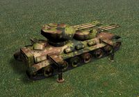
Dual Turret Tank
... available on turbo squid, the world's leading provider of digital 3d models for visualization, films, television, and games.
Supply
turbosquid
$1

supplies
... available on turbo squid, the world's leading provider of digital 3d models for visualization, films, television, and games.
3d_export
$5

black supply
...black supply
3dexport
black supply size: 57.9 x 29.2 x 34 sm
turbosquid
$20

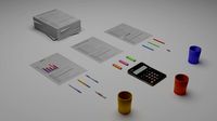
Office Supplies
...lty free 3d model office supplies for download as max and obj on turbosquid: 3d models for games, architecture, videos. (1273636)
3d_export
free
office supplies
...office supplies
3dexport
turbosquid
$8

Supply Drop
...e 3d model supply drop for download as fbx, obj, dae, and stl on turbosquid: 3d models for games, architecture, videos. (1663721)
turbosquid
$75

Supply Helicopter
... available on turbo squid, the world's leading provider of digital 3d models for visualization, films, television, and games.
turbosquid
$65
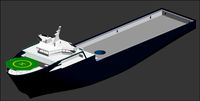
Supply Ship
... available on turbo squid, the world's leading provider of digital 3d models for visualization, films, television, and games.
turbosquid
$29
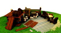
Village Supplies
... available on turbo squid, the world's leading provider of digital 3d models for visualization, films, television, and games.
turbosquid
$19

Power Supply
... available on turbo squid, the world's leading provider of digital 3d models for visualization, films, television, and games.
turbosquid
$5

school supplies
... available on turbo squid, the world's leading provider of digital 3d models for visualization, films, television, and games.
Front
archibase_planet
free

Front
...front
archibase planet
facade front bluff
front 3d01a - 3d model (*.gsm+*.3ds) for interior 3d visualization.
3d_export
$5
front fork
...front fork
3dexport
front fork
3d_export
$5
Front Desk
...front desk
3dexport
modern and minimal reception front desk
3d_ocean
$4
Medical Front
...medical front
3docean
horror low medical
medical front
3d_ocean
$5
Front Desk
...front desk
3docean
desk front office reception
office reception counter or front desk. cad file and obj file included.
3ddd
free

Axor WaterDream by Front
...r , waterdream , front
axor waterdream by front
3d_export
$5
front nut eye
...front nut eye
3dexport
front nut eye
3d_export
$5
front screw eye
...front screw eye
3dexport
front screw eye
3d_export
$5

front clamping device
...front clamping device
3dexport
front clamping device
archive3d
free
Front 3D Model
...rchive3d
facade front bluff
front 3d01a - 3d model (*.gsm+*.3ds) for interior 3d visualization.
Power
turbosquid
$100
power
...ower
turbosquid
royalty free 3d model power for download as on turbosquid: 3d models for games, architecture, videos. (1421990)
3d_export
$5

Power
...power
3dexport
3d_export
$5
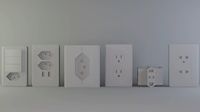
power outlets
...power outlets
3dexport
power outlets
3ddd
$1
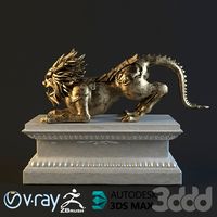
lion power
...lion power
3ddd
лев , статуя
lion power gold sculpture
3ddd
$1

Sea Power
...
компас , море , часы
часы с компасом sea power
3ddd
free
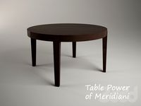
Meridiani / Power
...power
3ddd
meridiani , круглый
стол power производитель meridiani, диаметр 120,высота 67
3d_export
$5

Power Surge
...power surge
3dexport
the power surge is a all mesh carnival ride to lower in game part count and lag
turbosquid
$8
Airport Ground Power Unit (AXA Power )
... available on turbo squid, the world's leading provider of digital 3d models for visualization, films, television, and games.
turbosquid
$50

Power Houser
...rbosquid
royalty free 3d model power houser for download as on turbosquid: 3d models for games, architecture, videos. (1333800)
3d_export
$5

power outlet
...power outlet
3dexport
power outlet<br>format file maya 2018, 3d max 2017, obj, fbx
End
archibase_planet
free

Cigarettes end
...d
archibase planet
cigarettes end cigarette stub cigar-butt
cigarette-end - 3d model (*.gsm+*.3ds) for interior 3d visualization.
3d_export
$5
end table
...end table
3dexport
end table 3d model dimensions:(w)60cm×(d)60cm×(h)56cm
3d_export
$5
end table
...end table
3dexport
end table 3d model dimensions:(w)60cm×(d)60cm×(h)56cm
turbosquid
$10
End Table
...rbosquid
royalty free 3d model end table for download as max on turbosquid: 3d models for games, architecture, videos. (1570610)
turbosquid
$5
End Table
...urbosquid
royalty free 3d model end table for download as ma on turbosquid: 3d models for games, architecture, videos. (1622809)
turbosquid
$3
End Table
...rbosquid
royalty free 3d model end table for download as fbx on turbosquid: 3d models for games, architecture, videos. (1315115)
3d_export
$5

rope end ring
...rope end ring
3dexport
rope end ring
turbosquid
$2
End Tables
...
royalty free 3d model end tables for download as max and obj on turbosquid: 3d models for games, architecture, videos. (1706896)
turbosquid
$14
End Table
...lty free 3d model end table for download as max, obj, and fbx on turbosquid: 3d models for games, architecture, videos. (1403051)
turbosquid
$12
End Table
...lty free 3d model end table for download as max, obj, and fbx on turbosquid: 3d models for games, architecture, videos. (1574707)