Thingiverse
Dual extruder calibration test by Jim2
by Thingiverse
Last crawled date: 4 years, 6 months ago
Use for fine tuning the XY offsets of the second extruder.
Update 2016 May 3: I've been printing quite a lot of these while working on new extruders and hotends, and the time it took to print the original got quite annoying. So I've created a mini version without the numbers. It's a little harder to use but does the job and prints in under 5 minutes. Pegs are 1mm, so if you slice with 0.5mm width you should get a sensible tool path.
Update 2016 Apr 3: I added a V2 of the test which is functionally equivalent but adds a base to part1 so that I don't have to remember to add a raft each time. I also slimmed the design down a little by moving the Y axis in under the X axis, and renamed the parts to remind me which way around I normally assign them. V2 takes a little longer to print than V1, especially if you can manage without a raft, so use whichever works best for you.
Load both parts into your slicer/host software. Make sure that both are at the same XY position (some plater software will try and autoplace the two parts and mess up the alignment). In Repetier host the trick is to assign both parts to the same group using the "Object informations" dialog that pops up when you clock the cog icon to the right of the part name in the object placement tab. You also need to assign the parts to the right extruders. In Cura you need to use the "dual extrusion merge" right menu option by right-clicking on one of the parts after you load them. With Slic3r stand-alone it seems like you need to load the first part, then open the settings dialog and use the "load part..." button to associate the second part. Then assign the right extruder to each sub part in the object in the same settings dialog.
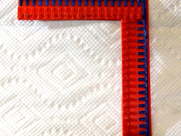
Each axis consists of 19 pairs of pegs. When the offsets are correct the middle pegs of each set will line up (the rest won't). It's best to get the offsets roughly right using a ruler or calipers, but if you're way off you can still measure the distance between the centre pegs to get started. Once the error is less than a millimetre you can find the best matching pegs and read the digit beside them. That's the correction needed in units of 0.1mm. You can either figure out the sign from the arrangement of the extruders or you can use good old trial and error :) In the photo of the V2 print (red abs and blue nylon), it looks like I need an additional .1 to .2mm of correction for both axes.
Update 2016 May 3: I've been printing quite a lot of these while working on new extruders and hotends, and the time it took to print the original got quite annoying. So I've created a mini version without the numbers. It's a little harder to use but does the job and prints in under 5 minutes. Pegs are 1mm, so if you slice with 0.5mm width you should get a sensible tool path.
Update 2016 Apr 3: I added a V2 of the test which is functionally equivalent but adds a base to part1 so that I don't have to remember to add a raft each time. I also slimmed the design down a little by moving the Y axis in under the X axis, and renamed the parts to remind me which way around I normally assign them. V2 takes a little longer to print than V1, especially if you can manage without a raft, so use whichever works best for you.
Load both parts into your slicer/host software. Make sure that both are at the same XY position (some plater software will try and autoplace the two parts and mess up the alignment). In Repetier host the trick is to assign both parts to the same group using the "Object informations" dialog that pops up when you clock the cog icon to the right of the part name in the object placement tab. You also need to assign the parts to the right extruders. In Cura you need to use the "dual extrusion merge" right menu option by right-clicking on one of the parts after you load them. With Slic3r stand-alone it seems like you need to load the first part, then open the settings dialog and use the "load part..." button to associate the second part. Then assign the right extruder to each sub part in the object in the same settings dialog.
Each axis consists of 19 pairs of pegs. When the offsets are correct the middle pegs of each set will line up (the rest won't). It's best to get the offsets roughly right using a ruler or calipers, but if you're way off you can still measure the distance between the centre pegs to get started. Once the error is less than a millimetre you can find the best matching pegs and read the digit beside them. That's the correction needed in units of 0.1mm. You can either figure out the sign from the arrangement of the extruders or you can use good old trial and error :) In the photo of the V2 print (red abs and blue nylon), it looks like I need an additional .1 to .2mm of correction for both axes.