Thingiverse
DRIVING A RELAY WITH AN ARDUINO by tarantula3
by Thingiverse
Last crawled date: 3 years ago
DRIVING A RELAY WITH AN ARDUINO
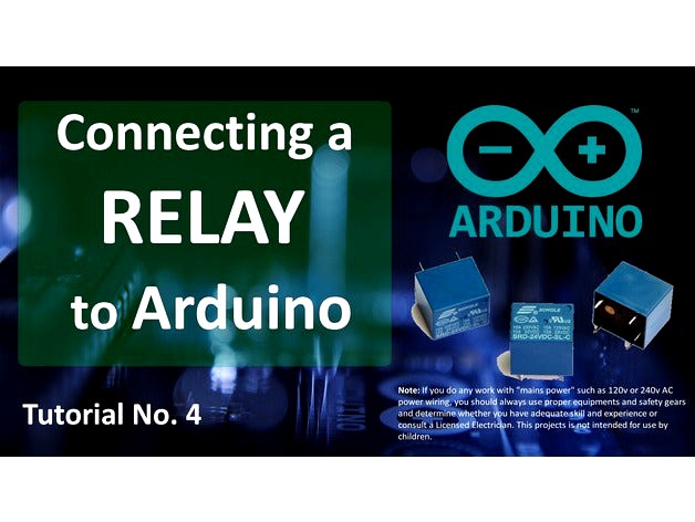
Hello everyone, welcome back to my channel. This is my 4th tutorial on how to drive a RELAY (not a relay module) with an Arduino.
There are hundreds of tutorial available on how to use a "relay module" but I could not find a good one that shows how to use a Relay and not a Relay module. So, here we are to discuss how a relay works and how we can hook it up to an Arduino.
Note: If you do any work with "mains power" such as 120v or 240v AC power wiring, you should always use proper equipments and safety gears and determine whether you have adequate skill and experience or consult a Licensed Electrician. This projects is not intended for use by children.
Step 1: Basics
A Relay is a large mechanical switch, which is toggled on or off by energizing a coil.
Depending on the operating principle and structural features relays are of different types, such as:
Electromagnetic Relays
Solid State Relays
Thermal Relays
Power Varied Relays
Reed Relays
Hybrid Relays
Multi-dimensional Relays and so on, with varied ratings, sizes and applications.
However, in this tutorial we will only be discussing about an electromagnetic relays.
Guide to Different Types of Relays:
https://en.wikipedia.org/wiki/Relay
https://www.elprocus.com/different-types-of-relays...
Step 2: My Relay (SRD-05VDC-SL-C)
The relay I am looking at is a SRD-05VDC-SL-C. It is very popular relay among Arduino and DIY electronics hobbyists.
This relay has 5 pins. 2 for the coil. Middle one is COM (common) and the rest of the two are called NO (Normally Open) and NC (Normally Close). When current flows through the coil of the relay, a magnetic field is created that causes a ferrous armature to move, either making or breaking an electrical connection. When the electromagnet is energized the NO is the one which is on and NC is the one which is off. When the coil is de-energized the electromagnetic force disappears and the armature moves back to the original position turning on the NC contact. The closing and releasing of the contacts results in powering on and off of the circuits.
Now, if we look at the top of the relay the first thing we see is SONGLE, it is the name of the manufacturer. Then we see the "Current and Voltage Rating": it is the maximum current and/or voltage that can be passed through the switch. It starts from 10A@250VAC and goes down till 10A@28VDC Finally the bottom bit says: SRD-05VDC-SL-C SRD: is the model of relay. 05VDC: Also known as "Nominal Coil Voltage" or "Relay Activation Voltage", it is the voltage necessary for the coil to activate the relay.
S: Stands for "Sealed Type" structure
L: is the "Coil Sensitivity" which is 0.36W
C: tells us about the contact form
I have attached the datasheet of the relay for more information.http://old.ghielectronics.com/downloads/man/20084...
Step 3: Getting Hands on a Relay
Let’s start by determining the relay coil pins.
You can do it either by connecting a multimeter to resistance measuring mode with a scale of 1000 ohm (since the coil resistance normally ranges between 50 ohm and 1000 ohm) or by using a battery. This relay has 'no' polarity marked on it since the internal suppressing diode is not present in it. Hence, the positive output of DC power supply can be connected to any one of the coil pins while negative output of DC power supply will be connected to the other pin of the coil or vice versa. If we connect our battery to the right pins you can actually hear the clicking sound when the switch turns on.
If you ever get confused in figuring out which one is NO and which one is NC pin, follow the steps below to easily determine that:
Set the multimeter to resistance measuring mode.
Turn the relay upside-down to see pins located at its bottom part.
Now connect one on the multimeter's probe to the pin in between the coils (Common Pin)
Then connect the other probe one by one to the remaining 2 pins.
Only one of the pins will complete the circuit and will show activity on the multimeter.
Step 4: Arduino and a Relay
The question is "Why to use a relay with an Arduino?"
A micro controller's GPIO (general purpose input/output) pins cannot handle higher power devices. A LED is easy enough, but large power items such as light bulbs, motors, pumps or fans required more sneaky circuitry. You can use a 5V relay to switch the 120-240V current and use the Arduino to control the relay.
A relay basically allows a relatively low voltage to easily control higher power circuits. A relay accomplishes this by using the 5V outputted from an Arduino pin to energize the electromagnet which in turn closes an internal, physical switch to turn on or off a higher power circuit. The switching contacts of a relay are completely isolated from the coil, and hence from the Arduino. The only link is by the magnetic field. This process is called "Electrical Isolation".
Now a question arises, Why do we need the extra bit of circuit to drive the relay? The coil of the relay needs a large current (around 150mA) to drive the relay, which an Arduino cannot provide. Therefore we need a device to amplify the current. In this project the NPN transistor 2N2222 drives the relay when the NPN junction gets saturated.
Step 5: Hardware Requirement
For this tutorial we need:
1 x Breadboard
1 x Arduino Nano/UNO (Whatever is handy)
1 x Relay
1 x 1K resistor
1 x 1N4007 High Voltage, High Current Rated Diode to protect the micro-controller from voltage spikes
1 x 2N2222 General purpose NPN transistor
1 x LED and a 220 ohm current limiting resistor to test the connectivity
Few connecting cables
A USB cable to upload the code to the Arduino
and general soldering equipments
Step 6: Assembly
Lets start by connecting the VIN and GND pins of the Arduino to the +ve and -ve rails of the breadboard.
Then connect one of the coils pin to the +ve 5v rail of breadboard.
Next we need to connect a diode across the electromagnetic coil. The diode across the electromagnet conducts in the reverse direction when the transistor is turned off to protect against a voltage spike or the backward flow of current.
Then connect the Collector of the NPN transistor to the 2nd pin of the coil.
The Emitter connects to the -ve rail of the breadboard.
Final, using a 1k resistor connect the Base of the transistor to the D2 pin of the Arduino.
Thats it our circuit is complete, now we can upload the code to the Arduino to turn on or off the relay. Basically, when +5v flow through the 1K resistor to the Base of transistor, a current of about .0005 amps (500 microamps) flows and turns on the transistor. A current of about .07 amps starts flowing through the junction turning on the electromagnet. The electromagnet then pulls the switching contact and moves it to connect the COM terminal to the NO terminal.
Once the NO terminal is connected a Lamp or any other load can be turned on. In this example I am just turning on and off a LED.
Step 7: The Code
The code is very simple. Just start by defining the digital pin number 2 of the Arduino as the Relay pin.
Then define the pinMode as OUTPUT in the setup section of the code. Finally, in the loop section we are going to turn on and off the relay after every 500 CPU cycles by setting the Relay pin to HIGH and LOW respectively.
Step 8: Conclusion
Remember: It is very important to place a diode across the coil of the relay because a spike of voltage (inductive kickback from the coil) is generated (Electromagnetic Interference) when the current is removed from the coil due to the collapse of the magnetic field. This voltage spike can damage the sensitive electronic components controlling the circuit.
Most Important: Same as capacitors, we always under-rate the relay to mitigate the risk of relay failures. Lets say, you need to work at 10A@120VAC, don’t use a relay rated for 10A@120VAC, instead use a bigger one such as 30A@120VAC. Remember, power = current * voltage so a 30A@220V relay can handle up to a 6,000W device.
If you just replace the LED with any other electrical device like fan, bulb, fridge etc., you should be able to turn that appliance into a smart device with an Arduino controlled power outlet.
Relay can also be used to turn on or off two circuits. One when the electromagnet is on and the second one when the electromagnet is off.
A Relay helps in Electrical Isolation. The switching contacts of a relay are completely isolated from the coil, and hence from the Arduino. The only link is by the magnetic field.
Note: Short circuits on Arduino pins, or attempting to run high current devices from it, can damage or destroy the output transistors in the pin, or damage the entire AtMega chip. Often this will result in a "dead" pin of the micro-controller but the remaining chip will still function adequately. For this reason it is a good idea to connect OUTPUT pins to other devices with 470Ω or 1k resistors, unless maximum current draw from the pins is required for a particular application
Step 9: Thanks
Thanks again for watching this video! I hope it helps you. If you want to support me, you can subscribe to my channel and watch my other videos. Thanks, ca again in my next video.
Similar models
thingiverse
free

Relais Box (with SRD-05VDC-SL-C)
...d-05vdc-sl-c)
thingiverse
relais box
relais : srd-05vdc-sl-c
low level trigger (5v)
to control high voltage devices (10v 250vac)
thingiverse
free

SRD Relai Arduino SRD 05VDC SL C
...srd relai arduino srd 05vdc sl c
thingiverse
small srd box
thingiverse
free

Songle Relay SPDT MODEL by WayneWeng
...odel by wayneweng
thingiverse
a relay 3d model of songle 5 pin srd-05vdc-sl-c.
songle relay spdt model.
step file available.
thingiverse
free

Arduino Relay Circuit by jmsstewart
...ino connect to both ground from relay power supply and ground from relay board. be welcome to modify and redistribute this board.
thingiverse
free

Laboratory power supply by Matti55
...multi-turn potentiometer for the converters;
two double switch to turn on and off each output;
normal (not adjust) +12v and +5v.
thingiverse
free

Slayer Exciter - Telsa Coil 1.2Kv
...lpful: https://youtu.be/zewh_op2cnk
some specs:
primary coil: 3.5 turns
secondary coil: 12 turns
output: 12000v 4ma
weight: 150gr
thingiverse
free

Automated Vacuum Switch by JacobRobotGuy
...dding more features in future and use it to switch not only cleaning devices but also other devices in many various applications.
thingiverse
free
USING AN LDR SENSOR WITH ARDUINO by tarantula3
.... if you want to support me, you can subscribe to my channel and watch my other videos. thanks, ca again in my next instructable.
thingiverse
free

Simple Adjustable Voltage Power Supply by MechEngineerMike
... switching regulator at amazon:https://amzn.to/2wwjkeo
(make sure to choose the option that has the led display & heatsink!)
thingiverse
free

DFROBOT 5A MODULE ENCLOSURE by FrancescoOnorati
...led high to turn the converter module on and low to turn it off.
cautions: the input voltage must be higher than output voltage.
Tarantula3
thingiverse
free
USING AN LDR SENSOR WITH ARDUINO by tarantula3
.... if you want to support me, you can subscribe to my channel and watch my other videos. thanks, ca again in my next instructable.
thingiverse
free

DIY - SOLAR BATTERY CHARGER by tarantula3
...lps you. if you want to support me, you can subscribe to my channel and watch my other videos. thanks, ca again in my next video.
thingiverse
free

DIY - ARDUINO BASED CAR PARKING ASSISTANT by tarantula3
...lps you. if you want to support me, you can subscribe to my channel and watch my other videos. thanks, ca again in my next video.
Relay
thingiverse
free

relay box for double relay
...relay box for double relay
thingiverse
just a simple box i made to hold a 2 relay board for my cnc machine.
thingiverse
free

relay box
...relay box
thingiverse
relay box for arduino
thingiverse
free

Relay Support
...relay support
thingiverse
protection against shock when touching wires on the relay.
thingiverse
free

Relay holder
...mount for an arduino relay. it works with the chenbo 1 channel relay module board shield high/low level trigger with optocoupler.
thingiverse
free

Relay mount
...e ky-019 style relay.
purhased: https://www.amazon.com/gp/product/b06xhj2pbj/ref=ppx_yo_dt_b_search_asin_title?ie=utf8&psc=1
thingiverse
free

Relay enclosure/box, 4channel relay box by davidk123
...relay enclosure/box, 4channel relay box by davidk123
thingiverse
enclosure box for 4 channel relays
thingiverse
free

Dual Relay case for 400V relay by muken
... relay holder for this relay
https://www.elfa.se/sv/effektrelae-foer-kretskort-rt-1co-ac-230v-32-5kohm-schrack-1393240/p/13721178
thingiverse
free

Relay Case by lukasclaus
...relay case by lukasclaus
thingiverse
relay case
thingiverse
free

Relay for life by 18mahars
...relay for life by 18mahars
thingiverse
relay for life
thingiverse
free

Relay Box by Thatcher88
...relay box by thatcher88
thingiverse
this is an enclosure to house 3 relays
Arduino
thingiverse
free

Arduino Mounts
...arduino mounts
thingiverse
mounts for arduino uno and hapkit arduino
thingiverse
free

Arduino Nano
...arduino nano
thingiverse
arduino nano
thingiverse
free

Arduino nano01
...arduino nano01
thingiverse
arduino nano
thingiverse
free

Arduino DUE
...arduino due
thingiverse
arduino due
thingiverse
free

Vise for Arduino
...vise for arduino
thingiverse
vise for arduino
thingiverse
free

Arduino - Arduino+ shield enclosure by caltadaniel
...to fit with a standard arduino uno or with an arduino and a shield (i have tested it with an ethernet shield and works very well)
thingiverse
free

arduino lab
...arduino lab
thingiverse
complete arduino lab
thingiverse
free

arduino UNO case (boitier Arduino uno)
...arduino uno case (boitier arduino uno)
thingiverse
arduino uno case with reset button.
thingiverse
free

Arduino Mountingplate
...arduino mountingplate
thingiverse
mounting plate for arduino uno.
rescale stl to 10% for right size printing
thingiverse
free

ARDUINO CASE by AGN
...arduino case by agn
thingiverse
case for arduino uno
you have to cut m3 threads for the arduino.
Driving
thingiverse
free

USB Drive / Flash Drive / Pen Drive Case by BrosJr
...usb drive / flash drive / pen drive case by brosjr
thingiverse
spare part for a broken usb drive case.
my mom´s request :-)
thingiverse
free

Turret Drive
...turret drive
thingiverse
drive key and housing
thingiverse
free

USB Flash Drive Holder of Drives by paxamime
...ot of flash drives for various purposes so while 20 drives may sound like a lot, this is only one of 3 that i am currently using.
thingiverse
free

Ender3 Direct drive duel drive mount
...have created for the ender3 and should fit the cr10 printers. this is for the duel drive mount version not the standard version.
thingiverse
free

Drive Shaft by RedMerlin
...drive shaft by redmerlin
thingiverse
a drive shaft.
thingiverse
free

Driving Message by Mariblueruby
...driving message by mariblueruby
thingiverse
cheeky driving message
thingiverse
free

G-Drive External Hard Drive Case by EvanVS
...ve case by evanvs
thingiverse
this is a case for an external usb harddrive.
this case is designed to fit the "g-drive"
thingiverse
free

MK2 Drive Bashguards
...mk2 drive bashguards
thingiverse
bashguards for the mk2 avio at gear drive!
thingiverse
free

Harmonic drive
...harmonic drive
thingiverse
harmonic drive i made, uses 7.9 mm steal ball bearings. make sure to split into parts before printing
thingiverse
free

Waterjet Drive
...waterjet drive
thingiverse
waterjet model
A
thingiverse
free

IKEA Vaxer net pot by khrazik
...ymore in my neighborhood, so i made my own. fits standard vaxer tubs. these are meant to be printed upside down with no supports.
thingiverse
free

Quiet control box for SKR 1.4 + cable mgmt layer. by Evilkoal
...thing into the electronics of the power supply.
let me know if anything is weird, but i haven't noticed anything not fitting.
thingiverse
free

UVA Mens' Basketball 2018-19 NCAA Trophy by the_qsr
...tube.com/watch?v=hxa3xd4dxcy
i've added a blank uva trophy in .stl and .obj for any other sports/years that you want to remix
thingiverse
free

Volcano Nozzle Case by garethps
...er nozzles. i could have just stretched it but then the number inserts wouldn't have fit properly, hence my first ever remix!
thingiverse
free

Savage Dragon - Image Comics by ZMilab
...s in my mini style.
if you want more models released weekly and access to exclusives join my patreon!
patreon.com/ziemba3d
enjoy!
thingiverse
free

Concordia and Britannia & Germania expansion boardgame insert by MitutoyoRaytek
...pacer2-v2.stl. i butchered my cardboard insert and turned it into a spacer.
spacer1-v2.stl is designed for printing in vase mode.
thingiverse
free

Renna by Legname
...renna by legname
thingiverse
renna in compensato da 3mm
thingiverse
free

Extension Cord Cable Mount Clip by max_davis
...x_davis
thingiverse
cable mount that fits a standard extension cord cable (up to 9mm). just use two screws or nails to mount it.
thingiverse
free

VESA monitor mount French Cleat by Rockster160
...ing/using this you claim all responsibility due to damage. use at your own risk!
fastened them to the monitors using m4*12 bolts.
thingiverse
free

GBS Zero Rain / Reverse Light IVA Angled Gasket by SeanWally
...pu.
the design includes a small seat adapter make sure that bolts used to secure the light are still mating at the correct angle.