Thingiverse
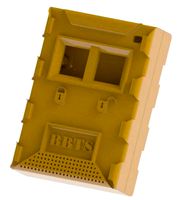
Double-Gang Receptacle Control by Magnifishot
by Thingiverse
Last crawled date: 3 years, 3 months ago
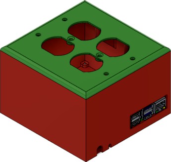
Use of a Raspberry Pi for controlling receptacle power via GPIO.
Requires:
Raspberry Pi 4, but should fit a 3 (perhaps even a 2, still)
4-port Relay board, w/ screw holes measuring 65.25mm x 45.25mm
Aukey, or similar, power block charger
6" Male-to-Male USB-C connector
3.5mm Male-to-Female audio jack
(13) M2.5x4mm screws, for general assembly
(4) 6-32 receptacle screws, for securing receptacles
(2) 6-32 oval head screws, for outlet cover.
Assembly
As this project mixes both high and low voltages, I will not be providing a how-to, due to fire risk. Do not proceed with this project if you do not have basic skills when dealing with high voltage. This project is a basic (8) GPIO manipulation: (4) for the LEDs and (4) for the relays, each of which is wired to interrupt the 'hot' wire of one receptacle. I won't add more detail than that.
Assembly is designed to be from the bottom, but it could be done in either fashion, I guess.
I've included (2) different covers for use, as well, a simplier design for no LEDs and a design with LEDs (shown)
Assembly Notes:
Note 1: Due to the offset caused by the Pi's location with respect to screw holes and the molded stand-offs on the bottom plate to help support the Pi and relay board, the bottom plate is not symmetrical. Therefore, two indexes have been placed on opposing sides to aid in locating the proper orientation.
Note 2: With the thickness of the PCBs and locations of the mounting tabs, I designed the system to be assembled with almost any M2.5 screw length. That said, there is one under the Pi that will interfere with the pins. To be safe, make sure to use nothing longer than M2.5x4mm.
Similar models
thingiverse
free

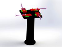
4 Relay Raspberry Pi Enclosure by skylinrcr01
...skylinrcr01
thingiverse
this is a case for the 3 relay board for the raspberry pi to shield from the high voltage carrying pins.
grabcad
free

Raspberry Pi GPIO Breakout board
...raspberry pi gpio breakout board
grabcad
raspberry pi gpio breakout board with pin header 2x20 pin male, 8.4 mm high
thingiverse
free

Raspberry Pi BlackBox by CyTheBorg
...r the plugins and the front. use 2.5mm screws to mount the pi and relay
here's a video in action https://youtu.be/ba-j6zfpl_o
thingiverse
free

Raspberry pi 4 + 4 Relais baseplate by fuleri
... + 4 relais baseplate by fuleri
thingiverse
first attempt to design kind of a baseplate for a raspberry pi and a 4 relay board
thingiverse
free

Relay Housing for Raspberry Pi by claancy
...ancy
thingiverse
housing and clip to attach a relay board to my raspberry pi sleeve case. the board is mounted with 2 m3 screws.
thingiverse
free

Raspberry Pi with dual relay board by steverjuk
...ual relay board by steverjuk
thingiverse
raspberry pi case with dual relay board, also designed to screw into cr-10 control box.
thingiverse
free

Case for Raspberry Pi with 4-Relay Board ks0212 by hdiessner
...s://astrohd.de
update: july, 5th 2018: added a tray for geeetech i3 / prusa to mount the case atop an i3 printer without screws.
thingiverse
free

Raspberry Pi 2/3 and Single-Relay Board Enclosure by davedeluxe
...
thingiverse
a simple case for the raspberry pi 2/3 and a relay board.
i use the relay to control my fan for my printer housing.
thingiverse
free

Sainsmart Relay with Power Outlet Enclosure by kazolar
...r on/off. this has supports for an outlet with threaded 6-32 screw holes and the relay is attached by regular motherboard screws.
thingiverse
free

Minimal Raspberry Pi Case
...a good fit for 5mm m2 bolts.
tested with raspberry pi b / 2b / 3b and 3b+.
the raspberry pi 4 may fit but i've not tested it.

Receptacle
turbosquid
$10

Trash Receptacle
... available on turbo squid, the world's leading provider of digital 3d models for visualization, films, television, and games.
3d_ocean
$4

Outdoor Trash Receptacles
...teel trash can trash receptacle
these are steel trash receptacles for outdoor use in recreational parks and other urban settings.
turbosquid
$25

Metal Trash Receptacle
... available on turbo squid, the world's leading provider of digital 3d models for visualization, films, television, and games.
turbosquid
$5

Tile Trash Receptacle
... available on turbo squid, the world's leading provider of digital 3d models for visualization, films, television, and games.
turbosquid
$5

Grill Trash Receptacle
... available on turbo squid, the world's leading provider of digital 3d models for visualization, films, television, and games.
turbosquid
$12

USB 2.0 Micro Connector Receptacle
...ro connector receptacle for download as ma, obj, c4d, and fbx on turbosquid: 3d models for games, architecture, videos. (1487256)
turbosquid
$10

MS Connector Receptacle 2 Pin Size 8
... available on turbo squid, the world's leading provider of digital 3d models for visualization, films, television, and games.
turbosquid
$10

MS Connector Receptacle 8 Pin Size 12
... available on turbo squid, the world's leading provider of digital 3d models for visualization, films, television, and games.
turbosquid
$25

22-single round power receptacles in 1 and 2 gang and materials
... available on turbo squid, the world's leading provider of digital 3d models for visualization, films, television, and games.
archibase_planet
free
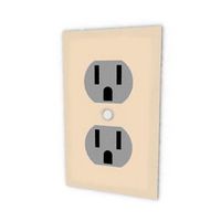
Outlet
...outlet archibase planet appliance receptacle convenience receptacle receptacle electrical outlet - 3d model for...
Gang
3d_export
$25
jin gang
...jin gang
3dexport
simple rendering of the scene file
3ddd
$1

Чайный сервиз Gange
... armani casa , сервиз
чайный сервиз gange, armani casa (италия)
turbosquid
$30

29-Duplex plate set 1 gang to 6 gang and materials
... available on turbo squid, the world's leading provider of digital 3d models for visualization, films, television, and games.
turbosquid
$32

Gang Construction Conveyor
...ree 3d model gang construction - conveyor for download as max on turbosquid: 3d models for games, architecture, videos. (1452373)
turbosquid
$119

Cartoon Faces Gang
... available on turbo squid, the world's leading provider of digital 3d models for visualization, films, television, and games.
turbosquid
$41

South Park Gang
... available on turbo squid, the world's leading provider of digital 3d models for visualization, films, television, and games.
turbosquid
$25
Swivel vice gang
... available on turbo squid, the world's leading provider of digital 3d models for visualization, films, television, and games.
turbosquid
$32

Gang Building - Primary Room
...ree 3d model gang building - primary room for download as max on turbosquid: 3d models for games, architecture, videos. (1452370)
turbosquid
$32

Gang Construction - Wood Shelf
...e 3d model gang construction - wood shelf for download as max on turbosquid: 3d models for games, architecture, videos. (1452380)
turbosquid
$32

Gang Construction - Arrow Tower
... 3d model gang construction - arrow tower for download as max on turbosquid: 3d models for games, architecture, videos. (1452378)
Double
3ddd
free
Double
...double
3ddd
double , sicis
диван double от итальянской фабрики sicis next art
3d_ocean
$5

double stairs
...double stairs
3docean
double stairs
double stairs
3d_export
$5

double handle
...double handle
3dexport
double handle
3d_export
$5
double fastener
...double fastener
3dexport
double fastener
3ddd
$1

double bed
...double bed
3ddd
двуспальная
double bed
design_connected
free

Chair Double
...chair double
designconnected
free 3d model of chair double
3ddd
$1

Double Leaves
...double leaves
3ddd
double leaves
кресло китайской фабрики double leaves. vray, 3dmax 2013, гамма 2.2, текстуры в комплекте.
3ddd
free
Люстра Double
...люстра double
3ddd
double , david chipperfield
2004
размеры в архиве
3d_export
free

couch - double
...couch - double
3dexport
couch double with texture and .psd files for personal customization
3d_export
$10
double layer double speed chain
...d chain
3dexport
double layer speed chain (design very detailed) 3d model drawing model file reference using solidworks software
Control
3d_ocean
$4
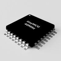
Controller TQFP32
...qfp32
3docean
chip controller cpu electronic gpu mcu micro controller silicon smd tqfp wafer
a micro controller in tqfp32 package
3d_ocean
$4
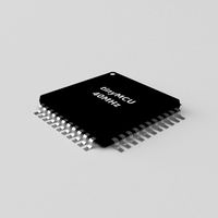
Controller TQFP44
...44
3docean
chip controller cpu electronic gpu mcu micro controller package smd tqfp tqfp44
a micro controller in a tqfp44 package
3d_export
$15
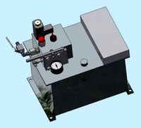
control unit
...control unit
3dexport
control unit
3ddd
$1
Yacht control
...yacht control
3ddd
yacht control
3d_export
$5
controle pgdm
...controle pgdm
3dexport
carcaca controle pgdm
turbosquid
free
controler
... available on turbo squid, the world's leading provider of digital 3d models for visualization, films, television, and games.
3ddd
$1

Control
...
http://www.schmitz-leuchten.de/html-ru/einzelleuchten-lampentyp-details.php?lamptype_no=700&group;=917&id;=731
3d_ocean
$4
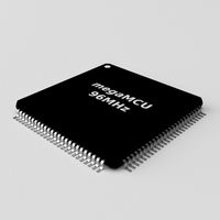
Controller TQFP100
...100
3docean
chip computer cpu electronic gpu mcu micro controller pin platine silicon wafer
a micro controller in tqfp100 package
3d_ocean
$4
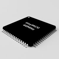
Controller TQFP64
...qfp64
3docean
chip computer cpu gpu mcu micro controller package silicon tqfp tqfp64 wafer
a micro controller in a tqfp64 package
3d_ocean
$7

Remote controller
... control switcher tv remote
remote controller for tv, sound systems etc easy to edit textures photo real rendered with mental ray