GrabCAD
DoF Analog Ventilator
by GrabCAD
Last crawled date: 1 year, 10 months ago
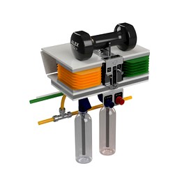
This is a concept for an analog ventilator to help address the urgent worldwide need for full-featured ventilators to fight the COVID-19 crisis. Patients in disparate locations and circumstances need similar levels of care, so this design attempts to decouple its essential functions from resources which may vary significantly between countries. Building on the Manley ventilator design from the 1950's, this design allows control of breathing rate, tidal volume, inspiratory pressure, maximum pressure, minimum pressure, and oxygen/air mix ratio without electricity or computer control.
Please note that this is purely a concept. This CAD does not represent a ventilator which can be used for a patient.
The intent for this design is to create a full-featured ventilator which can be successfully made and operated in a wide variety of environments with minimal compromises in functionality. This design attempts to avoid the assumption of extensive access to, or familiarity with, computer controls, 3D printing, programming, or other engineering disciplines. For example, this design allows production of critical components using 2D fabrication. The main structure, check valve assembly, bellows plates, and bellows can all be fabricated from sheet material, and often the same sheet. The seals and flaps of the check valve assembly are formed from single sheet of flexible material. This design does not preclude addition of electronics for telemetry, alarms, fault management, or patient-initiated cycling, but these aren't a predecessor to its successful operation.
Operating Sequence, starting with bellows fully extended and panel tilted upwards:
• When top panel is fully extended, slider on trigger bracket tidal volume gap contacts directional control valve toggle, pushing it up (stroke can be adjusted by moving and re-tightening slider on trigger bracket).
• Toggled directional control valve directs pressurized air away from air cylinder and to the PEEP cutoff valve chamber.
• Compressed air pushes PEEP valve cutoff flap against top of valve chamber, cutting off air flow from exhalation line to PEEP water volume. Meanwhile, ambient air flows through the needle valve into the air cylinder, with the retraction rate controlled by the degree of flow restriction through the needle valve.
• Panel falls under the weight of the assembly with rate controlled by ambient air flowing out of the cylinder and through the needle valve.
• Bellows are pressurized by the force applied by a fixed mass whose mechanical advantage is varied by moving the mass on top of the panel. Mix ratio of air and oxygen is set by the ratio of cross-sectional areas of air and oxygen bellows. Inspiration pressure can be verified by observing degree of movement of the outlet water column. Barotrauma is avoided by setting the total water column height in the outlet water column.
• Air and oxygen outlet check valves are pushed open by air exiting bellows. Inlet check valves are also pushed closed.
• Pressure, mix ratio, rate, and volume-regulated air is delivered to the patient.
• When top panel falls all the way down, top of edge of trigger bracket gap contacts directional control valve toggle, pushing it down.
• Toggled directional control valve directs pressurized away from PEEP cutoff valve chamber and into air cylinder.
• Compressed air flows to the air cylinder through the needle valve which controls extension speed through air flow restriction. The flap inside the PEEP cutoff valve chamber is pressed own by exhalation line pressure, opening the air channel to the PEEP water column.
• Bellows expand as panel is pushed up by air cylinder, pulling in both oxygen and air through check valves in the laminated valve assembly. On the exhalation line, air is permitted to flow through the PEEP close-off chamber and into the PEEP water column where it is vented at a controlled pressure.
• Pressure-regulated air is released from the patient. Air and oxygen bellows are refilled.
• Cycling rate is controlled by tuning flow in needle valve.
Benefits of the design include:
• Mechanism is driven by compressed air with common shop air pressures. Note that compressed air is only used to drive the mechanism. The unit draws ambient air for breathing from a separate shared line.
• Multiple ventilators can be run from shared manifolds of oxygen, air (for breathing), and compressed air. This can be done without compromising each unit's ability to individually control its volumes, rates, mix ratios, and pressures.
• The analog nature of device may help make it easier to verify functionality and settings at a glance. This also may make it more intuitive to people without extensive training or experience with computer controlled medical equipment.
Enhancements over the Manley ventilator include
• Using a-2D fabricated Designed Offset Joint to create deterministic 3D motion with a simpler structure.
• Use of folded bellows to allow creation of highly elastic, geometrically deterministic volumes using largely inelastic materials. This relates some of the constraints on bellows forming and material properties.
• Use of two bellows to control mix ratio rather than valve flow rate tuning to control mix ratio.
• Use of 2D stacked plates and a single sheet of flexible material with cuts and holes to create a valve assembly.
• Compressed air is toggled between the extension cylinder and PEEP closeoff valve, allowing breathing pressure to vary during inhale and exhale steps.
Some areas for improvement and forward work:
• Add locations for easier integration of electronics for telemetry, fault management, alarms, and patient-initiated breathing.
• PEEP cutoff valve should be closer to patient, reducing the amount of exhaled air which could be re-inhaled during next cycle
• Valve assembly needs screws for clamping shut. Plates likely have to be stiff to sufficiently distribute preload, or additional compliant material needs to be added to accommodate displacement of valve plates
• Origami bellows do not rigid fold, so some degree of compliance is necessary for folding behavior. It's likely possible to tune fold pattern such that it extends in an arc rather than linearly.
• If the PEEP cutoff valve seal isn't sufficiently tight under pressure, the compressed air may enter the breathing lines, pouring out the pressure relief bottle and potentially preventing continued operation of the unit. Pressure could be reduced to avoid this, but that also reduces pressure to the cylinder which could prevent it from cycling the bellows properly.
This was designed in Fusion 360 and the uploaded model is v118.
v101 eliminated two valve traces in the top plate of the valve assembly in v98.
v118 corrected label for directional control valve inhale/exhale assignment.
Thank you to the PEEP valve designer, Smart Water Bottle designer, and weight designer whose models I used in this design.
Similar models
grabcad
free

Nefos
...ta to doctor. this ventilator supply with oxygen tank and battery backup when unplug its still running in certain amount of time.
grabcad
free

BiPAP Ventilator with Mask Hookup
...proper respiration of patients. then the air is released into the surrounding environment. the patient has just taken one breath.
grabcad
free

Positive Pressure Ventilator
...ospital infrastructure. finally, the timer and switch value can be set to control both the breathes per minute and the i:e ratio.
grabcad
free

4 Person Ventillator
... bellow. this design is made with lightweight materials so that it can be easily moved around the hospital to where it is needed.
grabcad
free

OPENRESP(NISSASH)
...on startup
2) inlet oxygen detection
3) inhale exhale flow rate detection
4) temperature detection
key difference
cost 15000 bdt
grabcad
free

ChallengerVent
...controlled inhale valve, peep control valve, and exhale valve. bacterial filters will be added at outlet and/or inlet and outlet.
grabcad
free

Bi cylinder Air pump ventilator
...ifier valves and mask should be used to deliver air to patient
negative suction could be used with berating chambers if desired
grabcad
free

DOLC-01
...it will monitor incoming oxygen pressure and power levels along with battery backup life with alarms to notify of loss of either.
grabcad
free

Team Positive Pressure (Ventilator Mk. 1)
...valve.
by: ed chung, prerna gupta, james ho, jasmine kamdar, ali kight, aditya sudhakar, chen chia (charles) wang, jinfay yuan
grabcad
free

Bi Cylinder ventilator pump
...ifier valves and mask should be used to deliver air to patient
negative suction could be used with berating chambers if desired
Dof
turbosquid
free
hallway-DOF
... available on turbo squid, the world's leading provider of digital 3d models for visualization, films, television, and games.
3d_ocean
$4

DVD Cases with DOF
...th c4d r10 or later. great for displaying your dvds. i added proper depth of field which you will see when you render the scen...
3ddd
$1
interior column
...interior column 3ddd колонна classic column dof ...
3d_ocean
$8
3d model lacy umbrella and render scene
...model lacy umbrella and render scene 3docean 3d accessory dof lacy model render scene umbrella vray 3d model lacy...
3d_ocean
$18

Realistic Headphones
...headphones, great for interior visualization. highly detailed, great for dof ...
3d_ocean
$15
Ready collection V-ray tileable materials
...ready collection v-ray tileable materials 3docean cameras collection concrete dof fabric glass grid light max2010 metal black gloss mix...
3d_ocean
$12

Umbrella
...umbrella 3docean 3d accessory dof lacy model render scene umbrella vray 3d model of...
3d_ocean
$6

Nail Clippers
...model suitable for close-up render’s. included modo file hsa dof (depth of field) applied. included moi source file in...
3d_ocean
$9

Easy Render Scene For C4D/Vray
...scene for c4d/vray 3docean 3d rendering depth of field dof render scene scene through this complete scene you will...
3d_ocean
$5

Vray scene setup
...setup 3. 2 vray cameras, one of them with dof 4. vray lights 5. vitra panton chair model 6....
Analog
turbosquid
$1
Analog scape
... free 3d model analog scape for download as 3ds, max, and fbx on turbosquid: 3d models for games, architecture, videos. (1315807)
turbosquid
$25
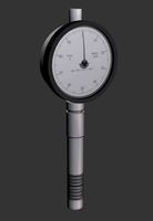
Analog Durometer
... available on turbo squid, the world's leading provider of digital 3d models for visualization, films, television, and games.
turbosquid
$3

playstation analog
... available on turbo squid, the world's leading provider of digital 3d models for visualization, films, television, and games.
design_connected
$7

Analog Wall Clock
...analog wall clock
designconnected
hay analog wall clock computer generated 3d model. designed by schneck, shane.
turbosquid
free

Vossen rim analog
... 3d model vossen rim analog for download as max, obj, and fbx on turbosquid: 3d models for games, architecture, videos. (1706126)
turbosquid
$7

Old analog multimeter
...analog multimeter for download as 3ds, max, obj, fbx, and dae on turbosquid: 3d models for games, architecture, videos. (1365964)
3d_export
$10

Analog Synthesizer 3D Model
... model
3dexport
keyboard moog synth retro vintage electronic techno music
analog synthesizer 3d model nillervision 59956 3dexport
cg_studio
$29
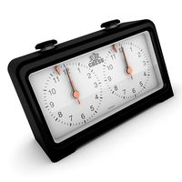
Analog Chess Timer3d model
...del
cgstudio
.obj .lwo .max .3ds - analog chess timer 3d model, royalty free license available, instant download after purchase.
turbosquid
$10

Dining Table Analog Set
...ritz hansen analog set for download as max, max, fbx, and obj on turbosquid: 3d models for games, architecture, videos. (1596537)
turbosquid
$24

Analog Cassette Audio Tape
...ssette audio tape for download as 3ds, max, obj, fbx, and stl on turbosquid: 3d models for games, architecture, videos. (1495255)
Ventilator
3d_export
$5

ventilation
...ventilation
3dexport
5 types of ventilation
3d_export
$10

ventilation
...ventilation
3dexport
5 types of ventilation and engineer communication
3d_ocean
$5
Ventilator
...pliance blower desk detailed electric electro fan hvac oscillating realistic table ventilator
high poly, very detailed ventilator
3d_export
$25

ventilator
...ventilator
3dexport
turbosquid
$20
Ventilator
... free 3d model ventilator for download as blend, fbx, and obj on turbosquid: 3d models for games, architecture, videos. (1612370)
turbosquid
$43

Ventilator
... available on turbo squid, the world's leading provider of digital 3d models for visualization, films, television, and games.
turbosquid
$25
ventilation
... available on turbo squid, the world's leading provider of digital 3d models for visualization, films, television, and games.
turbosquid
$4
Ventilator
... available on turbo squid, the world's leading provider of digital 3d models for visualization, films, television, and games.
3d_export
$5
ventilation and columns
...ventilation and columns
3dexport
ventilation and columns.<br>3 types of ventilation<br>2 types of columns
archive3d
free
Ventilators 3D Model
...ventilators 3d model
archive3d
ventilation ventilation equipment hvac