Thingiverse
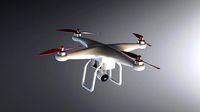
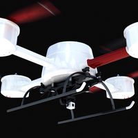
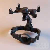
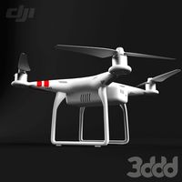
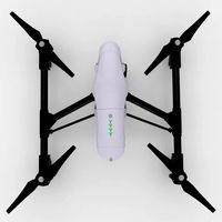
DJI Phantom 2 Vision Brushless Gimbal by Stoeckli
by Thingiverse
Last crawled date: 3 years ago
April 2, 2014 Update:
In-flight test of new holder GimbalBase8 (GimbalBase7 did have a design flaw which would not allow to mount the motor ;-)). Still jello effect. Then Felix found the solution: Video recorded with 25 frames have jello, 30 some and videos with 60 frames are just perfect (http://youtu.be/Qj32H0mnQfI). Thanks Felix for this insight! Now the design process is finished.
People report that they were not able get the rubber buffers from my previous post. It might be easier to get the M3 Flex-Loc buffers and use the Damper80 caps with M3/20mm screws in combination with the white stock buffers. I don't want to take credit for this damper design, as a similar one is used by other gimbal systems (check their product if 3d printing and soldering does not resonate with you ;-)).
March 30, 2014 Update:
New design GimbalBase7 with vertical PCB mount, 8 mm increased distance from cam to ground, 9.5 mm diameter for original dampers, no holder for additional tracker, moved cam 5 mm backwards. This design is based on feedback and not yet tested in air.
March 29, 2014 Update:
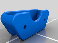
The key to the success of this gimbal is vibrational damping. The solution I use is to equip the stock dampers with a cap on each side (I added two parts, one for the top with 8 mm diam and one for the bottom with 7.5 mm diam), placing a 6 mm long rubber damper with M3 screw ends in the center. I had these dampers in my drawer but I don't have a part number or source. The other solution I saw on the web is to insert M3 Flex-Loc dampers (check google images) from the top into the stock dampers and a printed counter-part with a M3 thread from the bottom. Either solution leads to a siffer connection which is required to reduce oscillation.
These are the PID params I currently use - they are not optimized yet but are good starting values. Comments are welcome...
Roll: pwr 60, P 10, I 0.1, D 40
Pitch: pwr 50, P 10, I 0.1,D 40
Original Article:
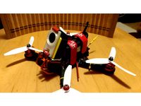
I bought a brushless gimbal for a Hero 3 (same as this: http://www.ebay.com/bhp/gopro-gimbal) and modified it to hold the original DJI Vision cam. My first project with SolidWorks, so please excuse for flaws in the design ;-).
Some details to the application:
I use an independent GPS tracker which sits also on board of the gimbal base plate.
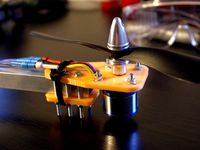
The PCB is mounted with the parts facing to the plastic, thereby protecting them from contact with the camera.
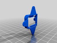
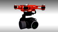
The sensor is mounted on the flat pad on top of the cam holder with double-sided sticky tape.
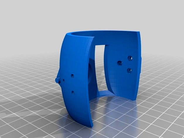
The camera snaps into the holder - you need some force to bend the flaps aside, but I was able to put it in and out multiple times without braking the PLA.
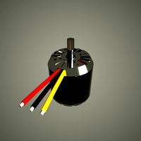
I get the power for the gimbal from the camera cable. I made a 3.5 mm 4-pin (important!) extension to the cam and split off the power. The shield carries Vcc and pin 3 GND. To clarify the connector pin-out: The tip and the adjacent ring are for the communication to the cam. The ring next to the shield is connected to Vcc (positive power).
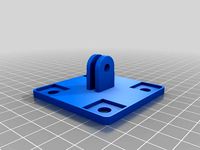
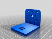
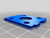
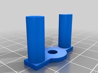
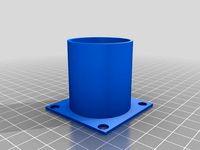
The base holder has a whole which serves to hold the female connector. The camera connects by a rectangular plug. See the images for more detail.
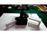
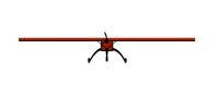
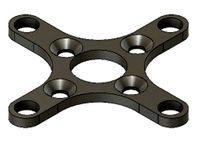
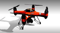
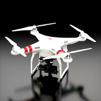
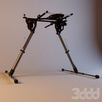
Mounting is critical for success. First, the holder was designed to place the gimbal in a position which brings the center of gravity right in the middle of the Phantom. So, if you have different gear, you'll have to shift the holder. I attached the holder to the copter by stiff dampers (the original ones are too soft) and placed silicone pads between copter and base plate (see images). These pads are critical, as without you'll end up with un-dampened vibrations. I'm still working on this, so maybe someone has a better design?
The space is tight and so the camera sits just a few mm above ground when facing a few angles up. So there's no need to modify the landing gear.
The servo output connects to the RX-Pitch input of the gimbal by ground and signal only (don't connect 5 V). Tilting all the way down is possible.
And finally, here are the SolidWorks 2012 files: http://www.stoeckli.net/?p=124
In-flight test of new holder GimbalBase8 (GimbalBase7 did have a design flaw which would not allow to mount the motor ;-)). Still jello effect. Then Felix found the solution: Video recorded with 25 frames have jello, 30 some and videos with 60 frames are just perfect (http://youtu.be/Qj32H0mnQfI). Thanks Felix for this insight! Now the design process is finished.
People report that they were not able get the rubber buffers from my previous post. It might be easier to get the M3 Flex-Loc buffers and use the Damper80 caps with M3/20mm screws in combination with the white stock buffers. I don't want to take credit for this damper design, as a similar one is used by other gimbal systems (check their product if 3d printing and soldering does not resonate with you ;-)).
March 30, 2014 Update:
New design GimbalBase7 with vertical PCB mount, 8 mm increased distance from cam to ground, 9.5 mm diameter for original dampers, no holder for additional tracker, moved cam 5 mm backwards. This design is based on feedback and not yet tested in air.
March 29, 2014 Update:
The key to the success of this gimbal is vibrational damping. The solution I use is to equip the stock dampers with a cap on each side (I added two parts, one for the top with 8 mm diam and one for the bottom with 7.5 mm diam), placing a 6 mm long rubber damper with M3 screw ends in the center. I had these dampers in my drawer but I don't have a part number or source. The other solution I saw on the web is to insert M3 Flex-Loc dampers (check google images) from the top into the stock dampers and a printed counter-part with a M3 thread from the bottom. Either solution leads to a siffer connection which is required to reduce oscillation.
These are the PID params I currently use - they are not optimized yet but are good starting values. Comments are welcome...
Roll: pwr 60, P 10, I 0.1, D 40
Pitch: pwr 50, P 10, I 0.1,D 40
Original Article:
I bought a brushless gimbal for a Hero 3 (same as this: http://www.ebay.com/bhp/gopro-gimbal) and modified it to hold the original DJI Vision cam. My first project with SolidWorks, so please excuse for flaws in the design ;-).
Some details to the application:
I use an independent GPS tracker which sits also on board of the gimbal base plate.
The PCB is mounted with the parts facing to the plastic, thereby protecting them from contact with the camera.
The sensor is mounted on the flat pad on top of the cam holder with double-sided sticky tape.
The camera snaps into the holder - you need some force to bend the flaps aside, but I was able to put it in and out multiple times without braking the PLA.
I get the power for the gimbal from the camera cable. I made a 3.5 mm 4-pin (important!) extension to the cam and split off the power. The shield carries Vcc and pin 3 GND. To clarify the connector pin-out: The tip and the adjacent ring are for the communication to the cam. The ring next to the shield is connected to Vcc (positive power).
The base holder has a whole which serves to hold the female connector. The camera connects by a rectangular plug. See the images for more detail.
Mounting is critical for success. First, the holder was designed to place the gimbal in a position which brings the center of gravity right in the middle of the Phantom. So, if you have different gear, you'll have to shift the holder. I attached the holder to the copter by stiff dampers (the original ones are too soft) and placed silicone pads between copter and base plate (see images). These pads are critical, as without you'll end up with un-dampened vibrations. I'm still working on this, so maybe someone has a better design?
The space is tight and so the camera sits just a few mm above ground when facing a few angles up. So there's no need to modify the landing gear.
The servo output connects to the RX-Pitch input of the gimbal by ground and signal only (don't connect 5 V). Tilting all the way down is possible.
And finally, here are the SolidWorks 2012 files: http://www.stoeckli.net/?p=124
Similar models
thingiverse
free
FPV HD Camera Body for VTIN by gschuto
...cap is to secure the cam from to lose it.
the body can be pushed on the gimbal cam holder. the inner slot dimensions are: 4x25mm.
thingiverse
free
SJCam M20 mount by gyjofi
...ple of "not-rigid" solution. the jello has gone with this mount. use battery strap and high density foam under the cam.
thingiverse
free
Yuneec Q500 Typhoon GoPro Style Gimbal Adapter Plate by Looney
...ch will give you the top plate and vibration dampers so you don't have to take the stock one apart the part # is yuncgo2gb102
3dwarehouse
free
UAV Gimbal Dampener
...uav gimbal dampener
3dwarehouse
rubber gimbal dampener model. 20mm tall, to scale. #damper #filming #gimbal #jello #uav
thingiverse
free
GIMBAL_-_Mobius Action Cam mount plate by 3Dlabor
...gimbal_-_mobius action cam mount plate by 3dlabor
thingiverse
this is an add-on for gimbal camera holder.
thingiverse
free

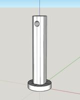
talon claw buffer tube stock pin
...talon claw buffer tube stock pin
thingiverse
stock pin for baam's buffer tube stock
thingiverse
free
Betafpv Z1 camera and VTX mount for Beta65/S whoop by dovcharov
...ount. then solder 5v to 5v wires , gnd to gnd, and video to video, or to osd pins on betafpv flight controller (if you have osd).
thingiverse
free
Wall Mount Buffer Holder (6in Pad)
...wall mount buffer holder (6in pad)
thingiverse
wall mounted holder for buffers. attaches to wall with screws.
thingiverse
free

Rodeo 110 1000TVL Camera Holder by Janbo
... see the pins on the pcb of the stock 600tvl cam.
i use the original walkera connection cable to connect the builtin transmitter.
thingiverse
free
VDQ250 Aomway Mounting shield by TenDutch
...
i liked the aomway cam mount by dingleberry but it didn't align with the stock plate from voodooquads so i designed one. :)
Phantom
design_connected
$13

Phantom
...phantom
designconnected
driade phantom computer generated 3d model. designed by emrys-roberts, peter.
design_connected
$11

Phantom
...phantom
designconnected
innovation randers phantom lounge chairs computer generated 3d model. designed by verner panton.
3ddd
$1

Phantom
...om
3ddd
пепельница
пепельница phantom. высоко полигональная фигура в форме грифона (стилизованная), материал v-ray золото внутри.
turbosquid
$9
Phantom
... available on turbo squid, the world's leading provider of digital 3d models for visualization, films, television, and games.
3ddd
$1
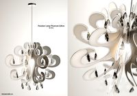
Pendant Lamp Phantom
...pendant lamp phantom
3ddd
kare
kare pendant lamp phantom
turbosquid
$30

phantom mountain
... available on turbo squid, the world's leading provider of digital 3d models for visualization, films, television, and games.
turbosquid
free
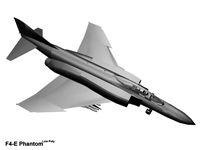
F4E-Phantom
... available on turbo squid, the world's leading provider of digital 3d models for visualization, films, television, and games.
3d_export
$25
RollsRoyce Phantom 3D Model
...rollsroyce phantom 3d model
3dexport
rolls-royce phantom rollsroycephantom
rollsroyce phantom 3d model lenar 19920 3dexport
3d_export
$5
phantom model drone
...phantom model drone
3dexport
3d modeling of phantom drone model. modeled in solidworks and saved in .stl and .sldprt formats
3d_export
$20

rollss roycee phantom 1963
...rollss roycee phantom 1963
3dexport
rollss roycee phantom 1963
Brushless
turbosquid
$4
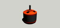
Brushless motor
...r download as 3ds, dxf, obj, xsi, wrl, fbx, dwg, dae, and skp on turbosquid: 3d models for games, architecture, videos. (1366202)
3d_export
$10
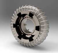
wheel and motor for mars rover
...last project: a mars rover concept. complete wheel and brushless electrical motor designed to attach to an atv or...
3d_export
$100
the volt futuristic ev hypercar
...future ! some design aspects : this is in-wheel (brushless hub) motors vehicle, for each motor the core part...
3d_export
$20
si cantik cargo plane for humanity medicine kit
...used for the tailboom. the electronic components used are brushless motor os 1000kv which can produce thrust 3kgas a...
free3d
free
N6375 Brushless Motor
...n6375 brushless motor
free3d
n6375 brushless motor
thingiverse
free

Tyro 79 brushless key
...tyro 79 brushless key
thingiverse
tyro 79 brushless key
thingiverse
free
Propeller antirotation brushless lock
...propeller antirotation brushless lock
thingiverse
propeller antirotation brushless lock
thingiverse
free
Brushless motor holder by NukeCraft
...brushless motor holder by nukecraft
thingiverse
brushless motor holder for bl3650
thingiverse
free
Brushless motor mount by robotbuilders
...brushless motor mount by robotbuilders
thingiverse
replacement mount for brushless motor.
thingiverse
free
Brushless motor mount by TarsVH
...brushless motor mount by tarsvh
thingiverse
a mount for a 2830 size brushless motor
Gimbal
turbosquid
$1
Yuneec Save Stick for Gimbal
... available on turbo squid, the world's leading provider of digital 3d models for visualization, films, television, and games.
3d_export
$20
splashdrone gimbal camera
...nsions. all textures used have been included. thank you for purchasing this model!! click on my username to see more of my models
3d_export
$40
splashdrone 3 plus with gimbal camera
...nsions. all textures used have been included. thank you for purchasing this model!! click on my username to see more of my models
turbosquid
$88
DJI Phantom 2 Quadcopter with gimbal for GoPro HERO4 or 3
... available on turbo squid, the world's leading provider of digital 3d models for visualization, films, television, and games.
3d_export
$5

concentrate box
...concentrate box 3dexport concealer box with handle and gimbal ...
cg_studio
$55
Drone Quadrocopter With Camera Rigged3d model
...fly wing propeller rc video camera sky dron spy gimbal gopro riged aircraft toy .obj .fbx .max .3ds -...
3d_ocean
$29
Drone Quadrocopter With Camera Rigged
...quadrocopter with camera rigged 3docean aircraft camera dron fly gimbal gopro propeller quadrocopter rc riged sky sport spy toy...
3ddd
free
Foucault's Iron Orb
...physicist léon foucault's gyroscope inspired our openwork globe. its double-gimbal frame is built of iron around a nucleus of...
thingiverse
free
Gimbal by tannermichael
...amera and gravity to self level. the gimbal uses .125" axles to pivot on. this gimbal was made using autodesk inventor 2015.
thingiverse
free
2020 Gimbal
...2020 gimbal
thingiverse
2020 gimbal
Dji
3ddd
free
Подвес DJI Zenmuse
... подвес
подвес dji zenmuse z15-5d для canon 5d mark ii/iiihttp://www.rcteam.ru/dji/zenmuse-z15-5d.html
3ddd
$1
шасси для рамы DJI S800
...еся шасси для рамы dji s800
dji s800 retractable landing skidhttp://www.rcteam.ru/dji/s800-retracting-landing-gear.html
3ddd
$1
DJI Phantom 2
... dji
450000 polys
швы корпуса могут показаться ошибкой моделинга, но это не совсем так!)
3d_ocean
$39

DJI Phantom3 Professional
...540 highly detailed model of the dji phantom3 professional quadcopter. the model is very highpoly (collapsed meshes, no modifi...
turbosquid
$1
dji osmo pocket
...
royalty free 3d model dji osmo pocket for download as blend on turbosquid: 3d models for games, architecture, videos. (1613550)
turbosquid
$98
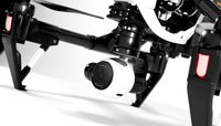
DJI Inspire 1
... available on turbo squid, the world's leading provider of digital 3d models for visualization, films, television, and games.
turbosquid
$9
DJI Charging hub
... available on turbo squid, the world's leading provider of digital 3d models for visualization, films, television, and games.
cg_studio
$39
DJI Phantom3 Professional3d model
... model
cgstudio
.max .obj - dji phantom3 professional 3d model, royalty free license available, instant download after purchase.
cg_studio
$39
DJI Inspire1 quadcopter3d model
...3d model
cgstudio
.max .obj - dji inspire1 quadcopter 3d model, royalty free license available, instant download after purchase.
3d_ocean
$39

DJI Inspire 1 quadcopter
...rtexcount: 270883 the model comes in the following formats: -max 2012 -obj (no materials), exported with blender preset includ...
Vision
3ddd
$1
Alona Vision
...alona vision
3ddd
журнальный
стол alona vision со стеклянной крышкой
design_connected
$25
Vision Sofa
...vision sofa
designconnected
capdell vision sofa computer generated 3d model. designed by dorigo, florenzo.
design_connected
$16

Vision Armchair
...vision armchair
designconnected
capdell vision armchair computer generated 3d model. designed by dorigo, florenzo.
turbosquid
$849
car vision
...turbosquid
royalty free 3d model car vision for download as on turbosquid: 3d models for games, architecture, videos. (1697160)
turbosquid
$45
vision sofa
...royalty free 3d model vision sofa for download as max and obj on turbosquid: 3d models for games, architecture, videos. (1425053)
turbosquid
$20
D-vision
...d
royalty free 3d model d-vision for download as max and fbx on turbosquid: 3d models for games, architecture, videos. (1360652)
turbosquid
$9
Vision furman
...yalty free 3d model vision furman for download as max and fbx on turbosquid: 3d models for games, architecture, videos. (1661274)
turbosquid
$1

Vision Panel
...lty free 3d model 3d vision panel for download as obj and fbx on turbosquid: 3d models for games, architecture, videos. (1483307)
3d_export
$18

barracks-vision 25
...barracks-vision 25
3dexport
barracks-vision 25<br>3ds max 2015
turbosquid
$5

Sword "Vision"
... available on turbo squid, the world's leading provider of digital 3d models for visualization, films, television, and games.
2
design_connected
$11
No 2
...no 2
designconnected
sibast no 2 computer generated 3d model. designed by sibast, helge.
turbosquid
$6
Cliff Rock 2-2
...uid
royalty free 3d model cliff rock 2-2 for download as obj on turbosquid: 3d models for games, architecture, videos. (1619161)
turbosquid
$29

Book variation 2 2
...3d model book variation 2 2 for download as max, obj, and fbx on turbosquid: 3d models for games, architecture, videos. (1366868)
turbosquid
$22
Classic baluster (2) (2)
...assic baluster (2) (2) for download as max, obj, fbx, and stl on turbosquid: 3d models for games, architecture, videos. (1483789)
turbosquid
$99

Smilodon 2 Pose 2
... available on turbo squid, the world's leading provider of digital 3d models for visualization, films, television, and games.
turbosquid
$20
Barrel Barricade 2-2
... available on turbo squid, the world's leading provider of digital 3d models for visualization, films, television, and games.
turbosquid
$6
Wall Trophy (2) (2)
... available on turbo squid, the world's leading provider of digital 3d models for visualization, films, television, and games.
turbosquid
free
Tire label 2 of 2
... available on turbo squid, the world's leading provider of digital 3d models for visualization, films, television, and games.
3ddd
$1

Кровать, 2 тумбочки, 2 светильника
...кровать, 2 тумбочки, 2 светильника
3ddd
кровать, 2 тумбочки, 2 светильника
нормальное качество
формат 3ds max
без текстур
3ddd
free

Кровать, 2 тумбочки, 2 светильника
...кровать, 2 тумбочки, 2 светильника
3ddd
кровать, 2 тумбочки, 2 светильника
нормальное качество
формат 3ds max
без текстур